

When planning an electrical system, it is important to know how thick the cables must be so that they are not heated by the current they are to transport.
It can also be good to be able to check if an existing electrical system has correctly dimensioned cables.
Fortunately, it is possible to calculate the cable area needed and it is also possible to calculate how much current can pass through an existing cable.
When sizing cables in an electrical system, there are a few things to keep in mind
Cable length
When calculating how thick the cable should be or how much current a cable can withstand, take into account the entire length of the cable in the circuit where the consumer is sitting.
In the electrical drawing below, you can see the lengths of the different cables and how much electrical current they should be able to transport. The electrical system is 12V DC and consists of four different circuits.
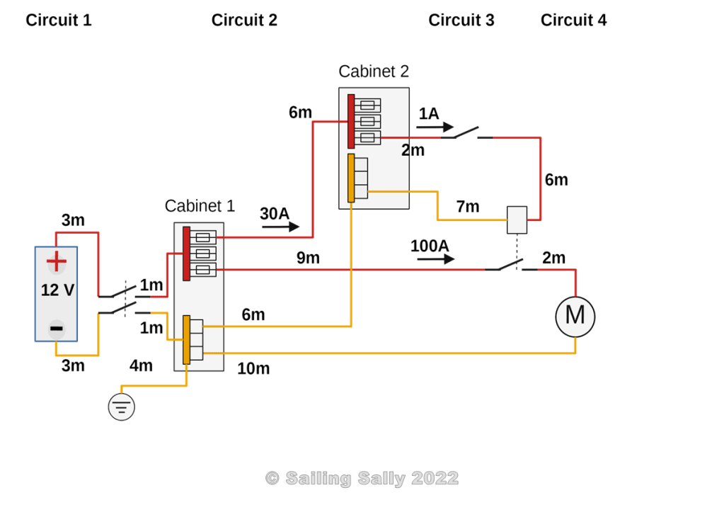
Compilation of cable lengths and current in the circuits in the picture above
| Circuit | Cable length (m) | Max current (A) |
| Circuit 1 From battery to Cabinet 1 | 3+1+3+1=8 | 100+30=130 |
| Circuit 2 From Cabinet 1 to Cabinet 2 | 6+6 = 12 | 30 |
| Circuit 3 The circuit from the Cabinet 2 switch that controls a relay contact to an electric motor | 2+6+7 = 15 | 1 |
| Circuit 4 The circuit from Cabinet 1 with the relay contact and the electric motor | 9+2+10 = 21 | 100 |
In addition, there is a connection to the boat’s ground point from the minus rail in Cabinet 1. That cable is 4m long. The current in that cable is zero as long as everything is in order with the boat’s electrical system.
The only time the current can be large is in the event of a lightning strike or in the event of a ground fault in the boat’s 230V AC.
As the possible current through the earth cable is short-lived, larger heating can be allowed and it does not need to be dimensioned according to the 4% rule. The strongest current will be generated by a lightning strike. More on this topic in a later article in this series.
Voltage drop
According to Swedish guidelines for electrical installation, the voltage drop in cables must be a maximum of 4% of nominal voltage.
SS 436 40 00 utg. 2 (Electrical installation rules) 525 (page 191) wrote: 525 Voltage drop in subscriber systems
NOTE – Normally the voltage drop in the installation should not exceed 4% of the nominal voltage. Larger voltage drops can be accepted for motors during start-up and for equipment with high connection current.
This rule applies to electrical systems with 230V AC and I make the assumption that it is good to have it as a rule also for electrical systems with 12V and 24V.
The table below shows the recommended voltage drop according to that rule.
| Nominal voltage/Voltage drop | 4% |
| 230V AC | 9.2V |
| 24V DC | 0.96V |
| 12V DC | 0.48V |
Low voltage cable or high voltage cable
Keep in mind that cables to be used in 230V AC must be designed for that voltage. Among other things, this means that they must be double-insulated if they are to be placed without protective containment.
Never use low voltage cables in electrical systems with 230V AC.
Cable colors
Follow the standard for what color the insulation on electrical cables should be, for Europe this means using the following colors on the various conductors in an electrical system.
230V AC
I have excluded the standard colors that can cause cables for phase to be confused with cables for protective earth and zero. I.e you should not use the color blue or yellow for phase and the ignition wire from an electrical switch.
| Cable | Color |
| Phase | Brown, Black, Gray |
| Zero (0V) | Blue |
| Protective earth (0V) | Yellow/Green |
| Ignition wire, from the switch to the consumer | White, Violet, Orange |
| After the consumer | Blue |
12V DC and 24V DC
If you have the opportunity, use yellow color on cables that have 0V, this means that there is no risk of confusing a black 0V cable with a black 230V phase cable.
| Cable | Color |
| Positive | Red |
| Negative (0V) | Yellow |
| Ignition wire, from the switch to the consumer | Red |
| After the consumer | Yellow or black |
Wire material
To calculate the cable size, you need to know what material is used in the cable, it is most common with copper cables in the boat’s electrical system. It does not matter if the cable is tinned or not.
Resistivity
There is a measure that indicates the resistance of a material per unit length. The measure is called Resistivity and indicates how much resistance a 1 m cable with an area of 1 mm2 has at 20 degrees Celsius. For each degree of temperature increase, the resistivity increases by 0.4%. This means that for a boat that is going to sail in the tropics, you need to calculate the cable area according to the resistivity you get at the temperature of 30° Celsius.
Another effect of the resistivity increasing with temperature is that if the cable is too weak and heats up when there is current in it, it gets increased resistivity and thus it heats up even more.
| Material | Resistivity (ohm/mm2) per meter of cable |
Copper 20° Celsius | 0.018 |
Copper 30° Celsius | 0.01872 |
Copper 40° Celsius | 0.01944 |
Calculate resistance
The resistance of a cable is calculated by the formula
Resistance = (Resistivity * length) / diameter of cable
This means that the resistance in 20m copper cable with an area of 10 mm2 will be
R = 20 * 0.018 / 10 = 0,036 ohm
Calculate the allowable current in the existing cable
Calculation of permissible current is done with Ohm’s law
U = R * I
If the voltage drop in the cable with a resistance of 0.036 ohms should be at most 0.5V, the maximum current is calculated as
Max current I = U/R = 0.5V / 0.036 ohm = 13.9A
Calculate cable area
If we know that the cable must withstand 50A and the length of the cable is 30m and that the voltage should not exceed 0.5V, how thick copper cable shall we choose?
NOTE! The entire length of the cable must be taken into account, ie the length from the battery to the consumer and back to the battery.
With Ohm’s law, we can calculate how much resistance the cable may have if the voltage drop is 0.5V at a current that is 50A.
R = U/I = 0.5V/50A = 0.01 ohm
The cable area for a copper cable with a resistivity of 0.018 ohm / mm2 per meter cable (at 20° Celsius) is calculated according to the formula
Cable area = Resistivity * Length of cable / Resistance = 0.018*30/0.01 = 54 mm2
If we do the same calculation for the temperature of 30° Celsius, which is a common temperature in the tropics, the cable area will be instead.
Cable area = 0.01872*30/0.01 = 56.16 mm2
For cabling in engine rooms, you need to count with resistivity for the temperature of at least 40° Celsius.
Example cable sizing
We use the picture with cable lengths, earlier in the article, as a basis for calculating how thick the cable should be in the different circuits. We calculate at the temperature of 40° Celsius, that it is a copper cable that is used, and that the voltage drop is 0.5V (4% of 12V).
First, you need to calculate the resistance of the cable for a voltage of 0.5V. To have some margin against too much heating in the cable and the fact that the boat will sail in the tropics, the cable area is calculated with the resistivity for copper at 40° Celsius which is 0.01944.
Resistance R is then calculated as 0.5V / max current in the circuit
Cable area = 0.01944 * cable length / maximum cable resistance in the circuit
| Circuit | Length | Current | Maximum resistance | Minimum cable area |
| Circuit 1 Fro battery to Cabinet 1 | 8m | 130A | 0.5V/130A =0.004 ohm | 0.01944*8m/0.004 = 39 mm2 |
| Circuit 2 From Cabinet 1 to Cabinet 2 | 12m | 30A | 0.5V/30A = 0.016 ohm | 0.01944*12m/0.016 = 16 mm2 |
| Circuit 3 The circuit from the Cabinet 2 switch that controls a relay contact to an electric motor | 15m | 1A | 0.5V/1A = 0.5 ohm | 0.01944*15m/0.5 = 0.5 mm2 |
| Circuit 4 The circuit from Cabinet 1 with the relay contact and the electric motor | 21m | 100A | 0.5V/100A = 0.005 ohm | 0.01944*21m/0.005 = 82 mm2 |
In practice, it is difficult to find a cable with exactly the same area as in the calculation. Round to the nearest larger area for a standard cable and use it.
If you are used to using a spreadsheet program like Excel or similar, it is easy to do the calculations of cable areas.
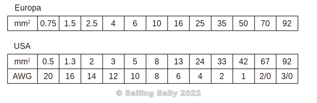
Standardized cable areas
Cables are manufactured with standard areas according to the table below. In Europe and many other countries, a metric standard is used where the area is specified in mm2. There are thicker cables in the standard, but they are impractical to install in a pleasure boat, so I have not included them in the table. If the thicker cable is needed, use 2 pcs of a thinner cable. If the cable dimensioning says that the cable should have an area of 130 mm2, use 2×70 mm2.
In the US, another standard is used where the size is specified as an AWG (American Wire Gauge) measure.
The table below shows the Metric and AWG standard areas. The table also shows the AWG cable area in mm2 and how the metric and AWG correspond to each other.

Du måste vara inloggad för att kunna skicka en kommentar.