

This article describes how a 12V or 24V DC alternator works and how to charge batteries in different circuits with the same alternator. You can also read about the so-called ”Load dump” and the load on the alternator when charging lithium batteries.
Parts of the alternator

- Drive belt pulley
- Housing with a cooling fan
- Rotor with inductive coils and discs
- Stator with inductive windings
- Housing with rotor brushes, rectifier, and triode bridge
- Charge regulator
- Protective cover
Generation and regulation of current
When the rotor’s inductive coils are energized, they create a magnetic field. When the rotor is set in rotation when the motor is running, the magnetic fields create a varying voltage in the stator coils (alternating voltage). The position of the coils and the construction of the rotor cause the stator to release a 3-phase voltage that must be rectified before it can be used in an electrical system with direct voltage.
How much current the generator creates depends partly on the voltage that the regulator puts on the coils of the rotor and partly on how fast it rotates. The higher the voltage the more current, the higher the speed (up to a certain limit), the more current the generator makes.
The regulator receives power from the generator via a so-called triode bridge. Before the engine has started, there is no power to be obtained from the generator and this has been solved by the rotor winding receiving power from the battery when the ignition of the engine is switched on. When the engine has started, the current from the triode bridge increases, which means that the voltage at the field winding of the rotor increases to just above the battery voltage. This means that there is no longer any current from the battery to the field winding.
Rectification
In the alternator, there is a so-called rectifier that converts the alternating current from the stator to a direct current with a nominal voltage of 12V or 24V. Which voltage is generated depends on which voltage the alternator is designed to generate.
Wiring diagram
The drawing below shows a standard wiring diagram for a 12V / 24V DC alternator.
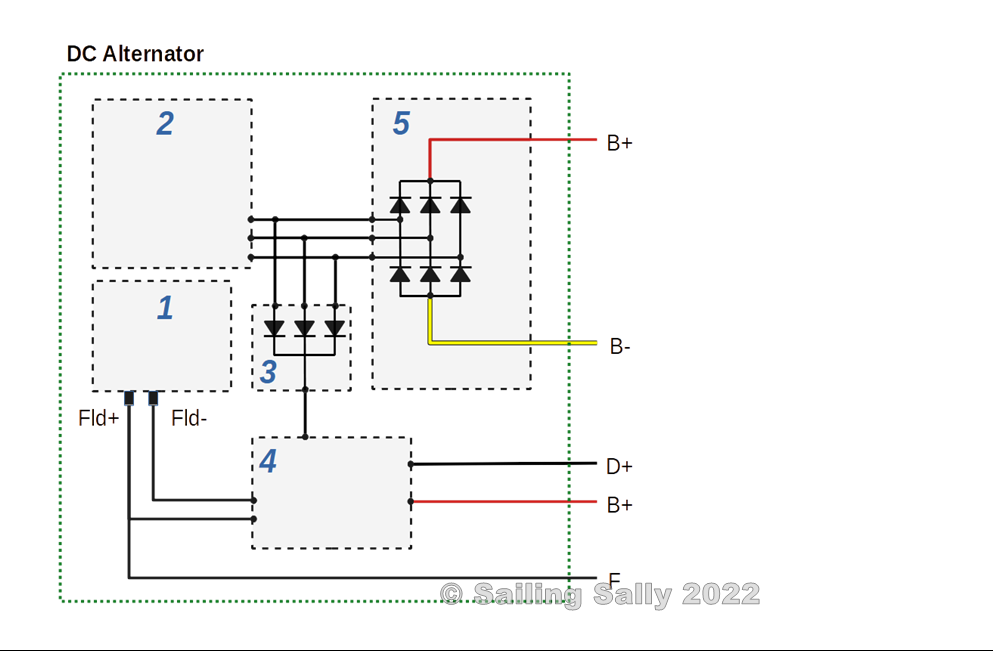
- Rotor with field windings and slip rings for transferring field voltage from the regulator to the rotor field windings.
- Stator with coils for generating current from the rotating magnetic fields from the rotor.
- Triode bridge for transmitting the positive part of the alternating voltage from the stator. Used by the regulator for energizing the rotor field winding.
- The regulator controls the voltage to the rotor’s field winding which determines how much current is to be generated. The more voltage the more current is generated.
- The rectifier of the alternating current from the stator to 12V or 24V direct current depending on the voltage the generator is designed to generate.
Generator sockets
B+
connected to the positive terminal of the battery (+12V). The connection is used by the controller to obtain the current voltage level of the battery and to supply the charging current to the battery.
If you want to connect a generator so that the battery outlet does not have contact with the engine block, the socket B- needs to be insulated from the generator housing.
D+
Connects to the engine ignition.
F
Some generators have this socket to control the voltage on the rotor field winding. This allows you to connect an external controller without modifying the generator.
W
Sometimes there is also this socket that indicates the generator RPM.
Charge two batteries
Often there is a 12V starter battery and a separate 12V Service battery that are connected in different electrical circuits.
If you want to be able to charge both batteries with the same 12V generator, you must build the electrical system so that power can be conducted from the generator to both batteries. Since the batteries in the different circuits will have different voltage levels, the design must prevent the current from being conducted from one battery to the other.
There are a few different technical solutions that prevent this
- Use a charge controller with two separate connections (most expensive)
- Use a battery separator with minimal voltage drop
- Use isolating diodes, they have about 0.5V – 0.2V voltage drop depending on the variety
Charge regulator for 2 different batteries
The best solution is to use a charge controller that can handle two types of batteries at the same time. This means that the circuits have no electrical connection at all (galvanically separated). The controller will probably first charge one battery and when it is fully charged the other battery will be charged. The reason is that the regulator controls the voltage of the generator according to which voltage the battery is charged with.
Battery separator
Next best is to use a battery separator that has a very low voltage drop (below 0.1V). This means that the generator will sense almost the same voltage as the battery.
There are some components called battery separators, but they have a higher voltage drop (around 0.5-0.2V). These are treated as a solution with isolating diodes described in the next section.
The charging current from the generator is distributed over the two battery circuits according to the resistance in the circuits (Ohm’s law and the case of parallel-connected resistors).
The built-in regulator usually has only one charging stage (BULK) which means charging with constant current (i.e. as much as the battery can receive) until a certain voltage is reached. With two batteries to charge, one of which is a LiFePO4, the power will in most cases be limited by the generator’s capacity.
The circuit with the lowest resistance receives the most current. As a result, the voltage sensed by the alternator is largely determined by the battery with the lowest resistance at the moment. But it does not matter since the charging regulator only has one charging stage (BULK). The important thing is that the charging voltage does not become too high for either of the batteries in the two circuits.
The picture shows the two charging circuits for 12V Start and 12V Service. Both circuits have approximately the same resistance in the cables and the resistance of the fuse R1fuse is lower than the resistance of the battery and does not affect the current distribution to any great extent. If you knew the resistance of the batteries, you could calculate how much current goes to each battery.
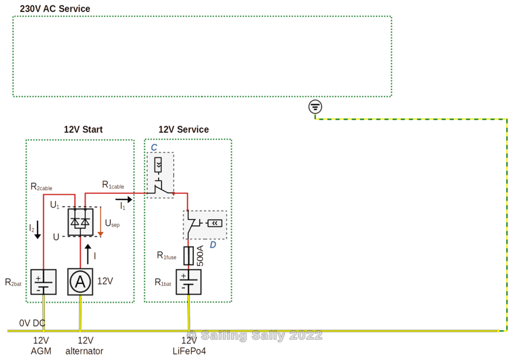
The more charged a lead-acid battery (AGM) is, the higher the resistance. A Lithium battery has basically the same resistance until it is almost fully charged (around 97% charged). A Lithium battery that is less than 90% charged always has lower resistance than a lead battery.
This means that the Lithium battery will receive most of the charging current until the battery is charged to at least 90%.
In this boat, the start circuit has an AGM battery (lead) and the service circuit has a Lithium battery. The lithium battery is set to disconnect the generator with the remote relay when it is 90% charged and then the starter battery will start to fully charge.
Isolating diodes
You can also use isolating diodes between the generator and each battery. Since the diodes have a voltage drop of around 0.2V – 0.5V depending on the type of diode, the charge regulator needs to compensate for this so that the voltage across the battery being charged is correct.
There are several variants of connections with diodes and if you are interested in these, I ask you to look up other sources for such information. The principle is the same, but the solutions will be different.
Discussion
Power distribution when using a battery separator
In these solutions, the batteries in the different subsystems are charged by the same alternator and this means that the charging current from the alternator is distributed over the two battery circuits according to the resistance of the circuits (Ohm’s law and the case of parallel-connected resistors).
The regulator of the alternator has only one charging stage (BULK) which means charging with constant current (i.e. as much as the battery can receive) up to a certain charging voltage. With two batteries to charge, one of which is a LiFePO4, the power will in most cases be limited by the generator’s capacity.
The circuit with the lowest resistance receives the most current. As a result, the voltage sensed by the generator is largely determined by the battery with the lowest resistance at the moment. It is OK because the controller only has one charging stage (BULK). The important thing is that the charging voltage does not become too high for either of the batteries in the two circuits.
The more charged a lead-acid battery (AGM) is, the higher the resistance. A Lithium battery has basically the same resistance until it is almost fully charged (around 97% charged). A Lithium battery that is less than 90% charged always has lower resistance than a lead battery.
This means that the Lithium battery will receive most of the charging current until the battery is fully charged. After that, only the starter battery is charged.
The BULK stage for a 12V LiFePO4 battery has a maximum battery voltage of around 14.2V, while an AGM battery has a maximum of 14.4V. Since the LiFePO4 battery in 12V-Service is charged first and then disconnected in this solution, the charge regulator for the generator can be set to the maximum voltage for the starter battery (14.4V) without the risk of damaging 12V-Service.
Power distribution with isolating diodes
This solution has the same characteristics as the battery separator except that the generator senses a battery voltage that is about 0.5V lower than that of the battery. This means that the batteries will not be charged as much.
You can compensate for this by increasing the regulator voltage to the batteries by 0.5V.
Load dump
In a solution like this, where a large current from an alternator can be broken with a switch, something called ”Load dump” occurs.
When the charge regulator notices that the voltage in the electrical system is rising, it lowers the voltage across the field winding of the rotor. But the alternator has energy stored in its rotating rotor and it does not disappear immediately when the voltage across the field winding is lowered by the regulator. The only way for the energy to disappear is as electricity from the alternator and this is what gives rise to an excess of energy when a large consumer is disconnected.
If there is no other large consumer who can ”take care” of the excess energy, the voltage will increase dramatically. With the power formula, P = U * I, it is possible to calculate the voltage increase. If the energy (P) is constant and the need for current decreases from 90A to say 15A, the voltage will be 6 times higher for a short time. That means around 70V in a 12V system and 140V in a 24V system!
This increase in voltage can cause, for example, the generator or the motor’s control electronics to break down.
In our electrical system, there is the starter battery that can take care of the excess electrical energy and the voltage increase is absent while the rotor field dissipates its energy and the regulator adapts the current to the new situation.
A ”Load dump” effect always occurs when an energy source produces more energy than consumers can handle. Therefore, it is important to have a regulator that shuts off the supply of electricity from solar panels and other energy sources that are connected to the electrical system. There are also special components you can install in the electrical system that takes care of an excess of energy.
Power output from the alternator
When charging a lithium battery, the current is high throughout the charging process. This means that a standard generator will be heavily loaded and risk overheating, especially if the generator has too low an RPM. This situation is avoided if the engine is accelerated to the speed of the boat’s cruising speed.
Charging at idle speed should always be avoided, most installations require a higher engine speed for optimal charging.
If the generator’s charge controller knows the generator’s temperature, the controller can make sure to limit the current from the generator when the temperature gets too high.

Du måste vara inloggad för att kunna skicka en kommentar.