
What is an electrical circuit?
An electrical circuit consists of a number of electrical components that are connected to electrical conductors so that they form an electrical circuit. In order for something to happen in the circuit, there must be an electrical energy source connected to the circuit.
The function of the electrical components and how they are connected determines how the circuit works. There are simple electrical circuits, for example in a flashlight and there are very complicated circuits, for example in a computer.
I dedicate this series of articles to relatively simple circuits with direct voltage or alternating voltage. The purpose is to supply electrical components on a boat with electricity. Some components may contain very complicated electrical circuits, but we do not need to know how they work.
In order to more easily understand how the electrical system is structured, it is conceivable that it consists of several circuits which in turn consist of sub-circuits that do not consist of any other circuits we need to construct or understand.
This boat has six electrical subsystems and each subsystem can be seen as a circuit. Each subsystem can be divided into smaller circuits (sub-circuits) which in turn can be divided into even smaller circuits. This can be done until there are only circuits left that do not need to be divided anymore.
When dividing into sub-circuits or simple circuits in boats, you can have some simple rules of thumb
- A circuit must always have its own fuse. There is one circuit that is exempt from this requirement and that is the circuit for the starter motor. This is what the EU rules for CE marking say (DIRECTIVE 2013/53/EU OF THE EUROPEAN PARLIAMENT AND OF THE COUNCIL of 20 November 2013 on recreational craft and personal watercraft, section 5.3 Electrical system)
”All electrical circuits, except engine starting circuits supplied from batteries, shall remain safe when exposed to overload”. - A sub-circuit circuit does not need to have a fuse as long as there is a fuse in one of the parent circuits that disconnects the power. The fuse in one of the parent circuits must cut off the power before there is a risk that the cables in the sub-circuit become too hot and start to burn in the event of a short circuit in it.
- A sub-circuit provides a certain function in the main circuit, eg starter motor circuit, charging circuit with the engine generator and batteries, power supply of the navigation system, direct power, lighting salon, and so on.
If there is a short circuit and there is no fuse, the wiring will be heated by the high current and in the worst case, it will start to burn.
The picture shows an electrical circuit with a battery, fuses, switches, and lamps. Red lines are cables from battery plus to lamps. Black lines are cables from lamps to battery terminals.
Examples of circuits
The picture shows an electrical circuit with a battery, fuses, switches, and lamps. Red lines are cables from battery plus to lamps. Black lines are cables from lamps to battery terminals.
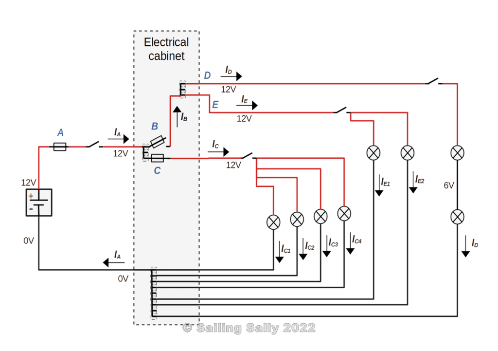
Circuit A
The electrical drawing shows an electrical system consisting of a 12V main circuit A which is supplied with electricity via a fuse that can handle the current IA and a switch. Circuit A consists of two sub-circuits B and C.
The current IA in the circuit is the sum of the currents of the sub-circuits IB and IC.
Circuit B
The B circuit consists of a fuse switch and two sub-circuits D and E.
The current in circuit B is the sum of the currents ID and IE which passes the sub-circuits D and E. This means that the fuse in the circuit must withstand the current IB.
Circuit C
Circuit C consists of a fuse and a switch and four 12V lamps in parallel. A parallel connection allows each lamp to light up as long as it is intact, even if the other lamps are broken. Since the lamps are connected in parallel, they have the same voltage, but they can have different effects, which means that they can draw different amounts of current. How much current it draws can be calculated with the power formula P = U*I, see the previous article on Ohm’s law.
The current in circuit C is the sum of the currents IC1, IC2 >, IC3, and IC4 through the lights in the circuit. This means that the fuse in the circuit must withstand the current IC.
Circuit D
The circuit D consists of a switch and two 6V lamps connected in series. The lamps have the same power and thus the same resistance. Then the voltage across each lamp will be 6V (Ohm’s law). The current in the circuit is ID and it passes through both lamps. How much current passes through the circuit can be calculated with the power formula P = U*I, see the previous article on Ohm’s law.
Circuit E
Circuit E consists of a switch and two 12V lamps connected in parallel. Since the lamps are connected in parallel, they have the same voltage, but they can have different effects, which means that they can draw different amounts of current. How much current it draws can be calculated with the power formula P = U*I, see the previous article on Ohm’s law.
The current in circuit E is IE i.e. the sum of the currents IE1 and IE2 .

Du måste vara inloggad för att kunna skicka en kommentar.