
This article describes the symbols used in the electrical drawings in Part 3 – Subsystems.
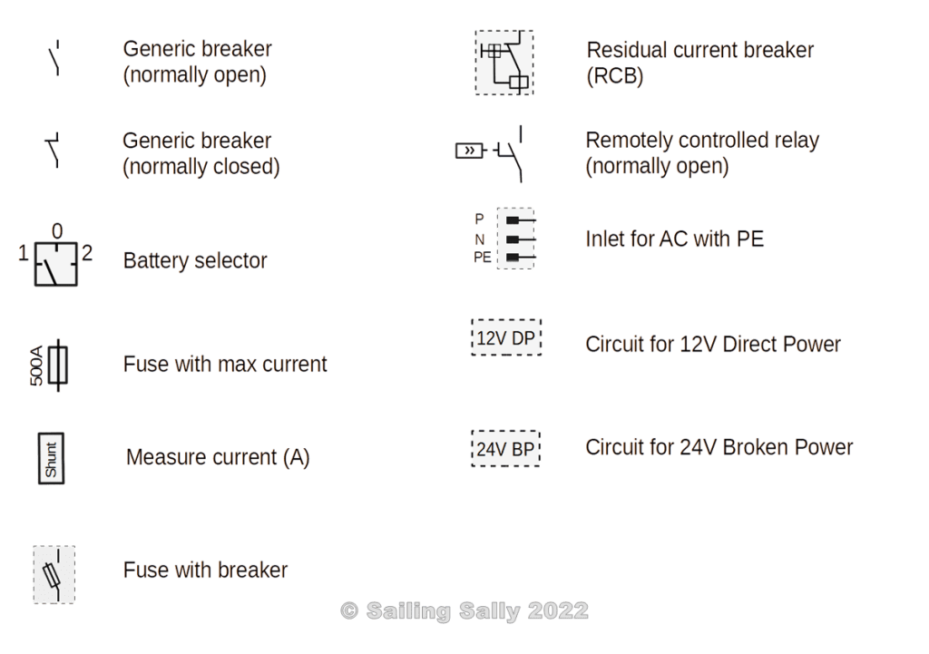
Some symbols were already used in the previous article and are described there. This image contains the symbols that are used in the electrical drawings in this article.
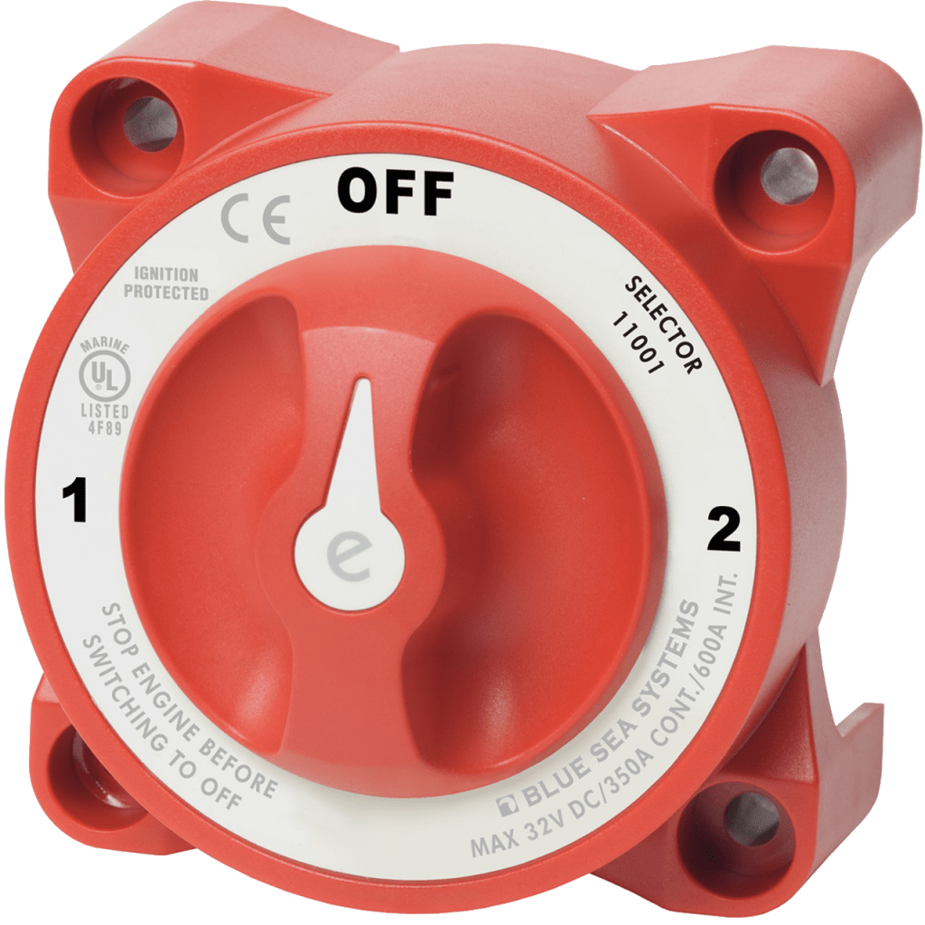
Battery selector
This is an electrical component that makes it possible to choose which battery to connect to an electrical circuit.
NOTE! There are battery selectors that have a position where both batteries are connected in parallel, which causes the battery with the lowest voltage to discharge the other battery.
It can say 1+2 or Both in that position. Do not use one if you have different types of batteries in the circuits or if they can have different charge levels.
Electrical circuit for direct power, DP
This circuit has no main power switch, which means that when the battery is connected, there is power in this circuit.
In order not to risk the service battery running out when you have a circuit like this, the boat needs to be equipped with an automatic charger that does not require connection to shore power, eg solar panels or wind power with sufficient power to keep the battery charged.
Equipment like refrigerators, bilge pumps, and alarms are connected in this circuit. These do not have manual switches in the control panel, however, they can advantageously be connected via circuit breakers that can be operated manually in order to be able to switch off the power to them. It also makes it easier to troubleshoot if a fuse is found to be broken.
Electrical circuit for broken power, BP
This circuit has a main switch that connects it to a battery.
The consumers connected in this circuit are connected via a fuse in the electrical cabinet and in some cases a switch in the cabinet. Examples of such consumers are navigation systems, plotters, VHF, and freshwater pumps. These switches should be equipped with an indicator light that illuminates when the consumer is receiving power.
Earth leakage breaker with fuse (RCBO), jordfelsbrytare
RCBO, Residual current breaker with overcurrent protection.
A component in a 230V AC system that breaks the circuit to the consumers when the current starts to go to earth. This can be caused, by a person coming into contact with a live part and then current is conducted to earth through the person, which is life-threatening. A working earth leakage circuit breaker disconnects the current before it becomes dangerous for a human being.
The picture below shows a double pole earth fault circuit breaker. The fact that it is a double pole means that both phase and zero are broken in the event of a fault.
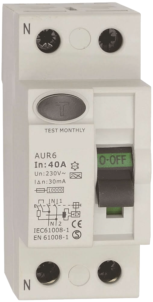
In this case, it also has a built-in fuse that causes it to break the voltage when the current becomes too large, which is the case with, for example, a short circuit of the circuit.
In its normal position, it is closed and conducts power.
Fuse
The symbol does not indicate whether the fuse is fast (breaks immediately when the current becomes too high), slow (it can withstand more current for a while before it breaks the current), or which technology is used. However, it is often used for so-called melt fuses. These are fuses that have a thin metal conductor that melts when too much current flows through it. There are different types of melt fuses, the picture below shows some different varieties that are common on board.
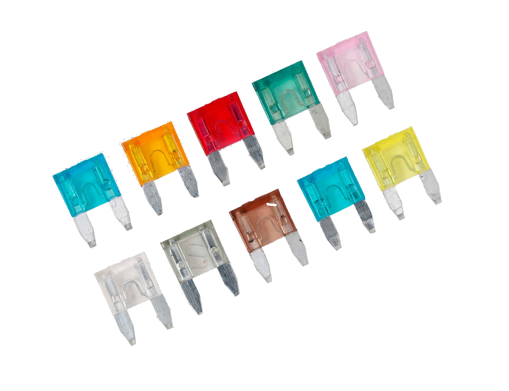
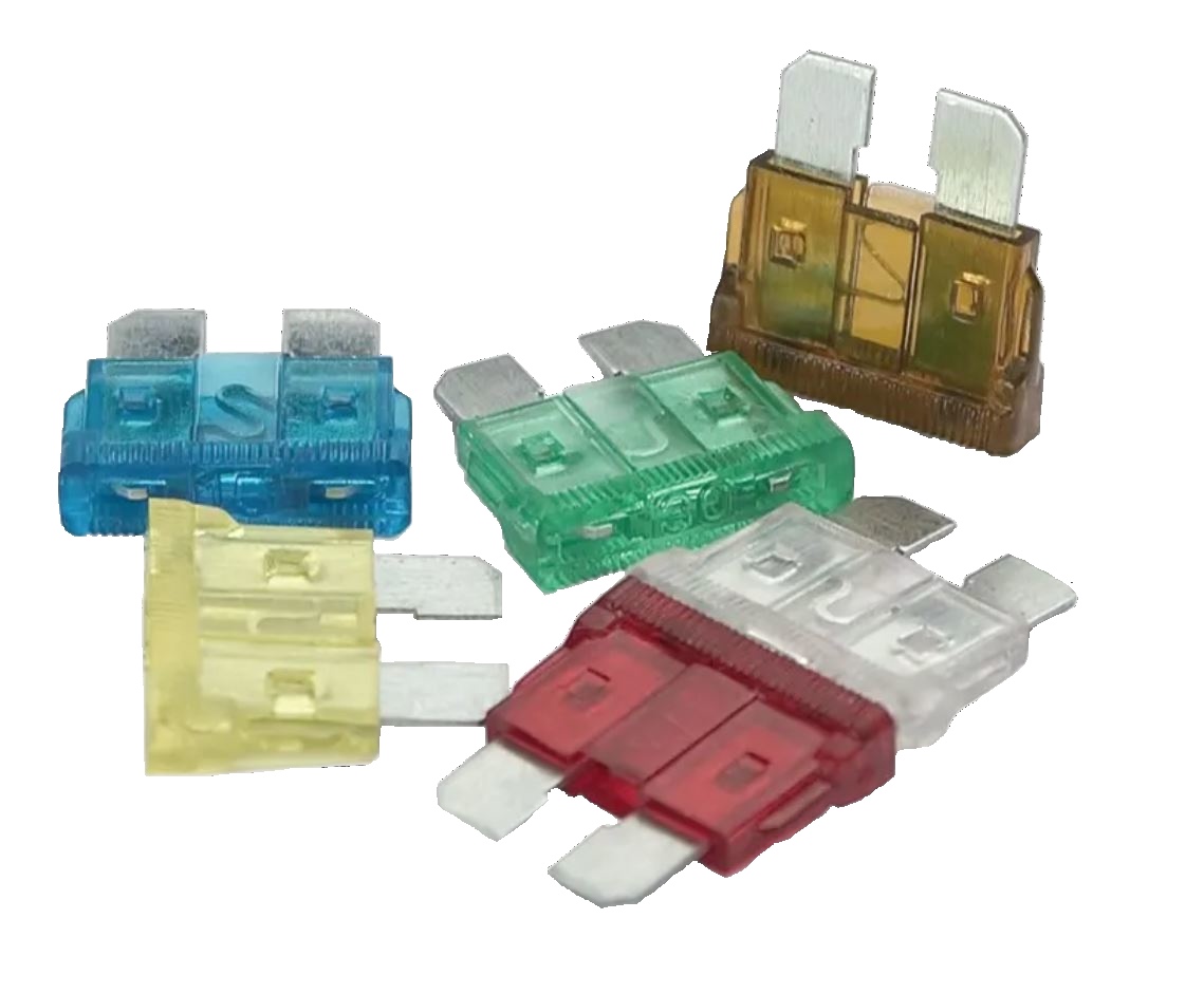


It is important to be able to see if a fuse is intact. Fuses with a thin wire should be located in a fuse holder that indicates with an LED if the fuse has blown. Automatic fuses usually have a button that changes position and some large fuses with the melting part located so that it is easy to see if it has melted or not.
Fuses are made of a metal that has a higher resistance when the temperature increases, which makes them even warmer and thus even higher resistance. In this way, the resistance is low when the current is within the fuse margin. The higher current the fuse must withstand, the lower the resistance the fuse must have in order not to cause voltage drops and heat generation, see the article about Ohm’s lag.
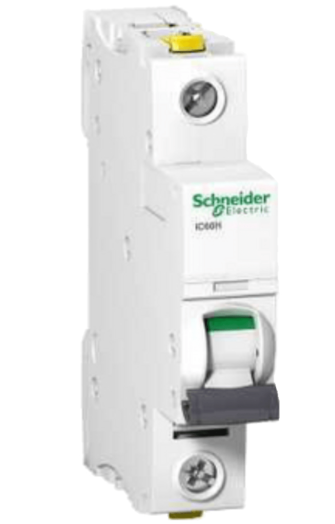
There are also so-called automatic circuit breakers that are based on technology other than a metal wire that melts. This means that it does not need to be replaced when the current has been too high. The picture shows a 230V circuit breaker
Fuse with a max current
This symbol represents a fuse that can withstand a certain maximum current before it breaks the current.
Fuse with breaker
A fuse that is combined with a switch. This means that the switch can be opened either manually or when the power becomes too large. This symbol means that the power switch is open in its normal position (does not conduct current).
Generic breaker (normally closed)
This is a switch of some kind and in its normal position, it is closed which means that it conducts current. When activated, it opens and the power is cut off.
Generic breaker (normally open)
This is a switch of some kind and in its normal position, it is open which means it stops the power. When activated, it closes and begins to conduct current.
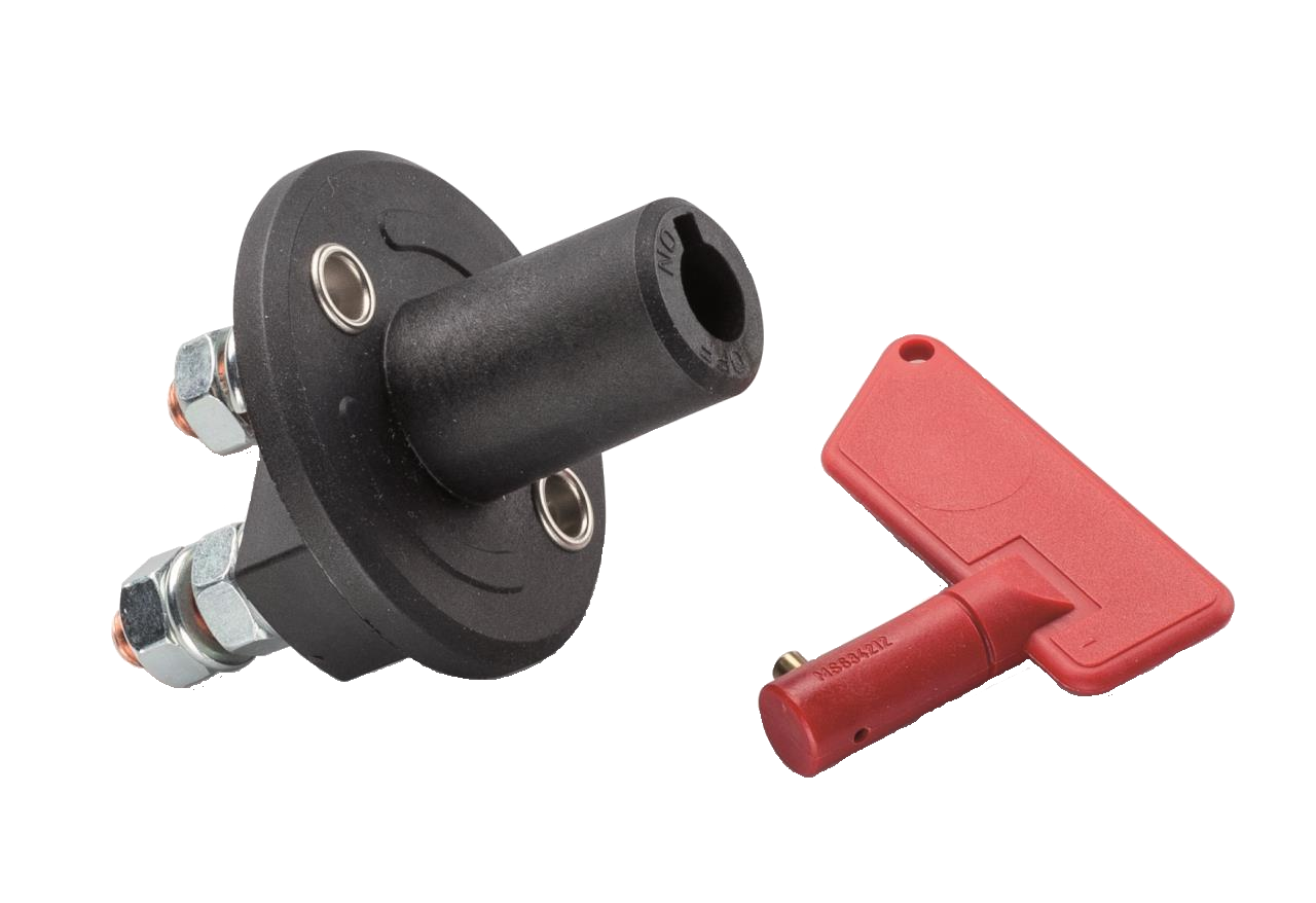
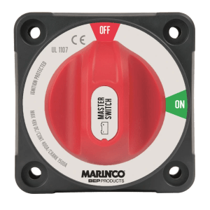
The image below shows two common types of main switches for boats.
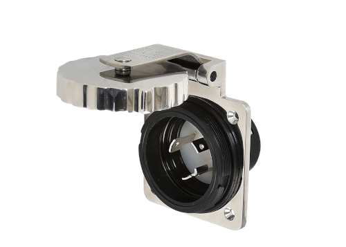
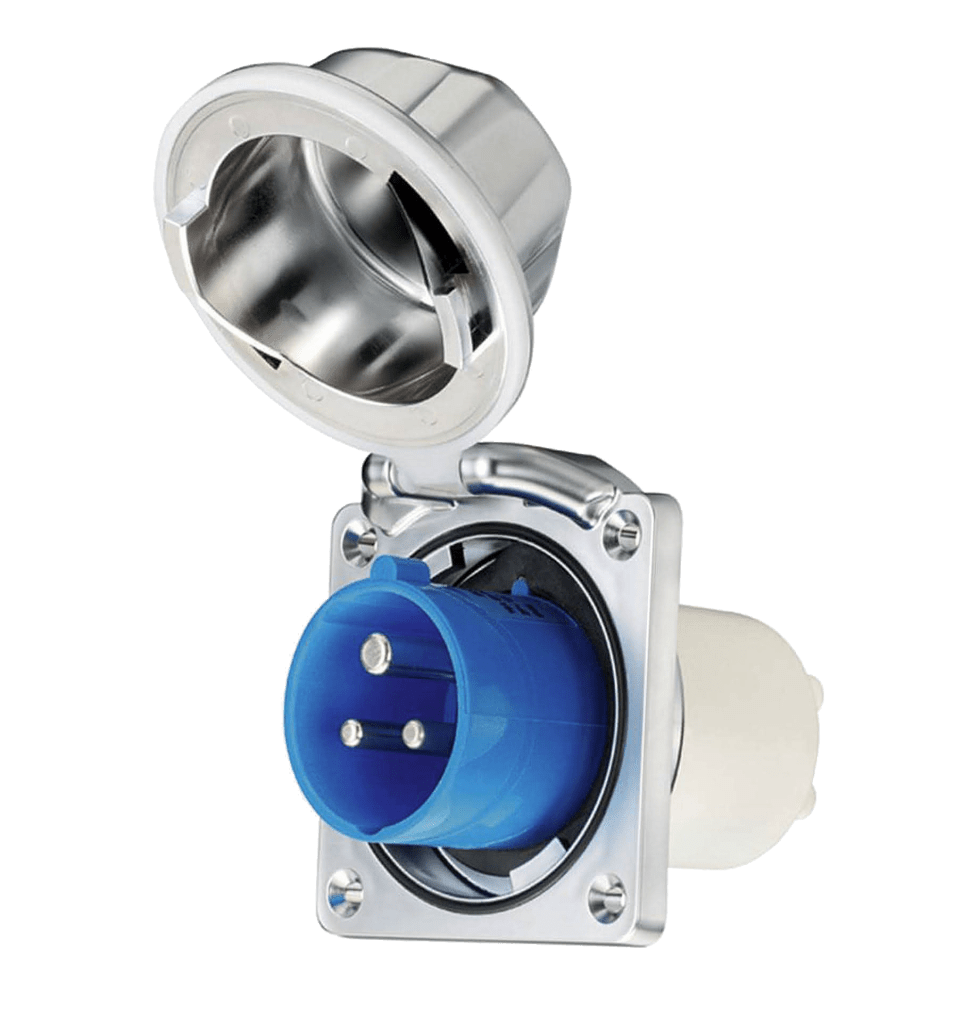
Inlet for AC with PE
Plug socket for alternating voltage with the connection of protective earth. The symbol does not indicate the type of socket (indoor, outdoor, shore power, etc.)
The picture below shows two common types of shore power connections for boats.
Relay
A relay is an electrically controlled switch that is connected to two different circuits, one control circuit, and the controlled circuit. The contacts marked with 85 and 86 are connected to the control circuit and are used to open/close a switch in the relay. The current in the control circuit is much weaker than the current in the controlled circuit. Connectors 87 and 30 are connected to the switch for the strong current in the controlled circuit. The picture below shows a relay for 24V that can break a current up to 200A.
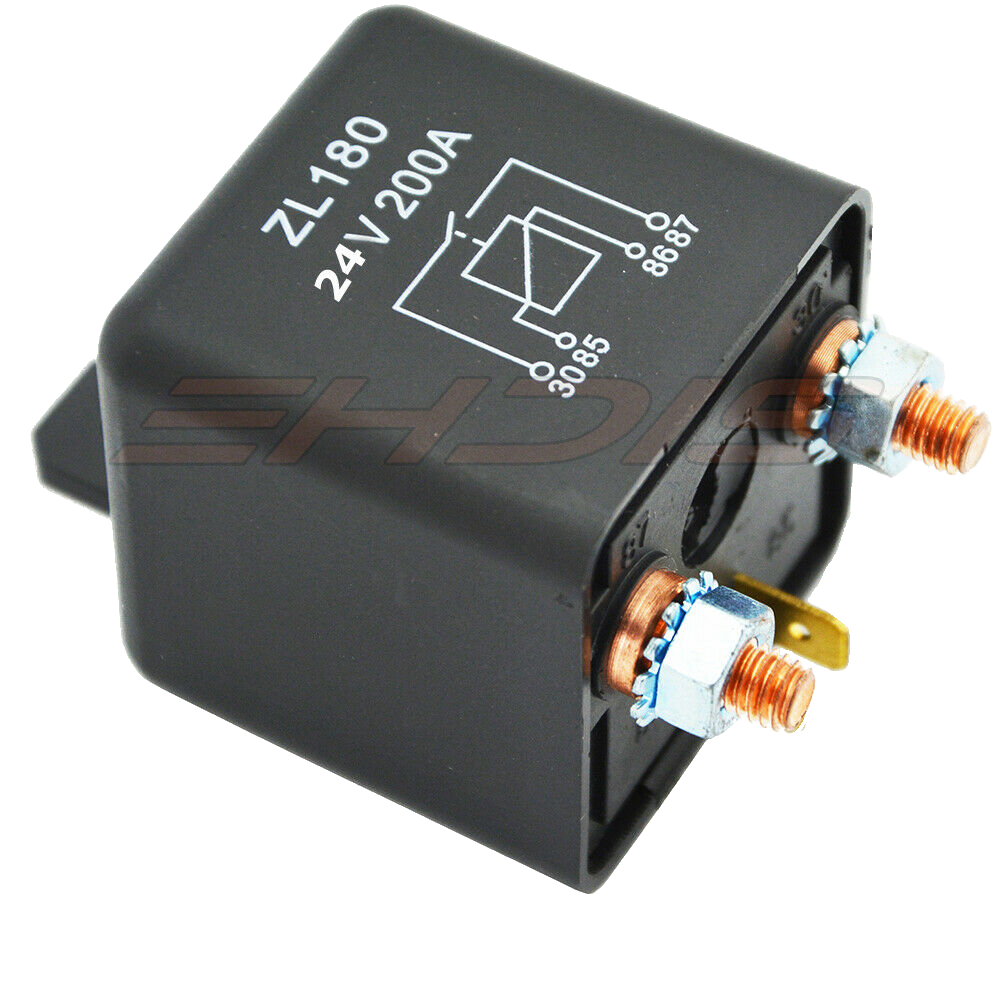
The contacts on a relay are marked with numbers and all relays of the same type have the same markings.
- 85 is connected to the minus side of the control circuit
- 86 is connected to the plus side of the control circuit
- 87 is connected to the minus side of the controlled circuit
- 30 connects to the plus side of the controlled circuit
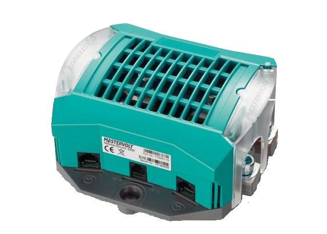
Remotely controlled relay
The fact that the relay is ”remote-controlled” means that the control circuit is replaced by a network connection which means that the relay can be controlled by any other equipment connected to the network. The picture below shows such a ”relay” that can break a current of 6A in the controlled circuit.

If you need to be able to break a stronger current, you can easily combine this relay with a more powerful relay that does not have a network connection. The picture below shows how such a solution is used for the remote-controlled relay C in the subsystem for 12V Service.

Shunt, measure current
A shunt measures how much current passes in or out of a battery. This is done by measuring the voltage drop across a very low and accurate resistance in the shunt. A low resistance gives a low voltage drop even when the current is large. The voltage drop in a typical shunt for 500A is approximately 50 mV (0.05V) at maximum current.
Some models are connected to the negative cable, while others are connected to both plus and minus.
The shunt should be placed close to the battery or battery bank that it measures. Then the voltage drop between the battery and the shunt will be as small as possible.
The images below show shunts that are connected to a network. These shunts have a built-in ability to also keep track of the battery’s charge level and send out the information on the network along with power consumption.
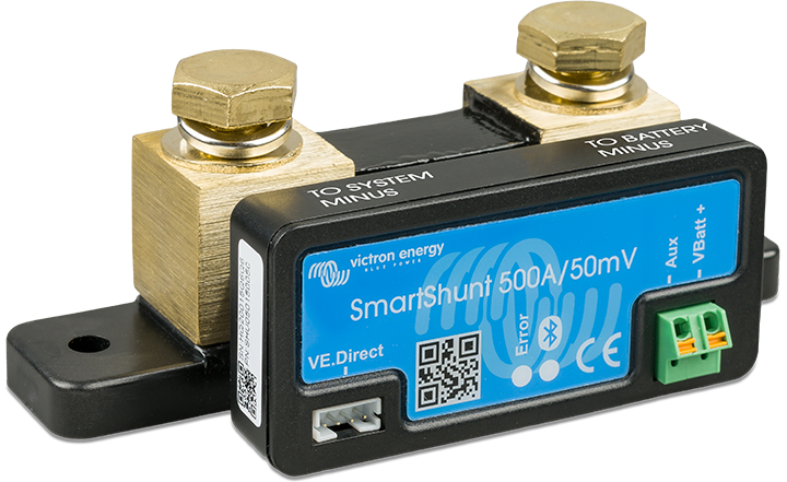
Some network-connected shunts can also measure the battery temperature with a sensor that is attached to the battery and connected to the shunt, which means that battery temperature can also be sent out on the network.
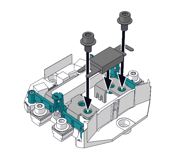
The electrical drawings in this series of articles use network-connected shunts that connect both plus and minus, which means that the shunt can also function as a fuse and measure battery voltage. The picture below shows a shunt where you can mount a fuse on the plus conductor.

Du måste vara inloggad för att kunna skicka en kommentar.