
In this article, you can read more about the different forms of AC systems used in Europe and the United States.
Alternating current
In an electrical system that has alternating voltage, the polarity of the voltage varies several times per second and follows a sine curve. Europe and the United States use alternating voltage in their electrical systems, but they have different standards.
The voltage varies between its maximum and minimum values according to a sine curve. It is also stated how often the voltage changes polarity every second, eg 50 times / second (Hz).
The nominal voltage of the system is calculated according to a mathematical formula, RMS (root mean square). RMS indicates the effective value of the voltage during an oscillation. This allows you to use the RMS voltage when calculating resistance, current, and power as if it were a direct voltage.
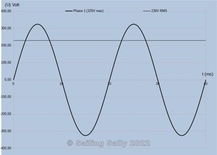
In Europe, the nominal voltage is 230V while the maximum voltage is +325V and the lowest voltage is -325V.
The picture below shows how the voltage varies with time in a system with 230V 50Hz.
Europe
When an alternating current is transported in a cable, 3-phases are used up to households and shore-side in marinas. In the property’s / marina’s electrical cabinet, the three phases are wired to form three 1-phase systems.
System with 3 phases in Europe
In a 3-phase system, there are 5 conductors in the cable and they are called Phase 1 (P1), Phase 2 (P2), Phase 3 (P3), Zero (N), and Protective earth (PE). The voltage difference is 230V between a phase and Zero.
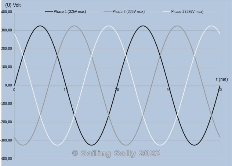
The picture below shows how the voltage varies in a sinusoidal form in the three different phases in a 3-phase AC voltage system 50 Hz. The oscillation in the phases is evenly offset from each other.
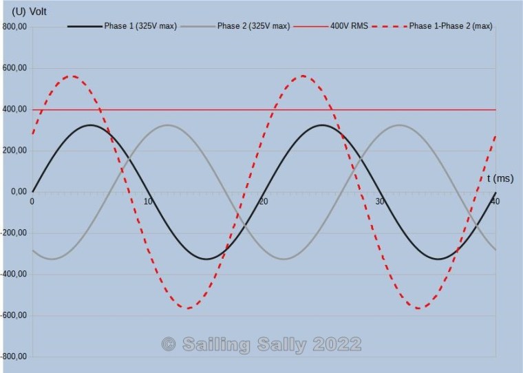
However, the voltage difference between the two phases is 400V. This is because the voltage change in the phases does not occur simultaneously.
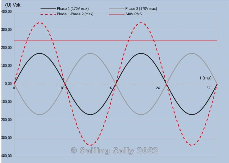
The image below contains the voltage for two phases (Phase 1 and Phase 2) and a dashed curve, Phase 1-Phase 2, which shows the voltage difference between the two phases.
The straight line at 400V shows the RMS voltage between the two phases.
Systems with 1 phase in Europe
From a European system with 3 phases, you can create a system with 1 phase by connecting a phase, neutral, and the protective earth.
There are 3 conductors in a 1-phase electrical system and they are called Phase, Neutral, and Protective Earth or Ground. The voltage difference between phase and neutral is 230V RMS and the polarity is changed 50 times per second.
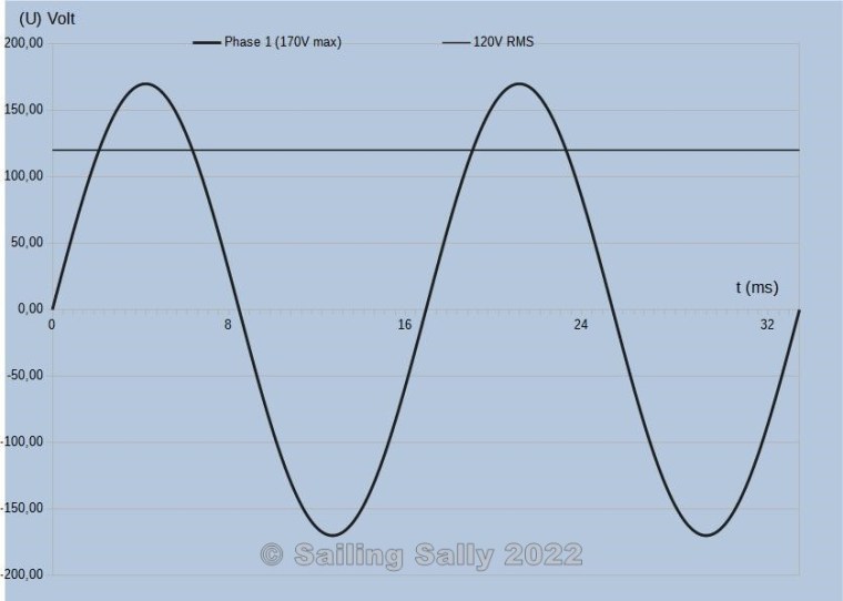
The picture below shows how the voltage variation in an electrical system with 1-phase. Note that the RMS voltage is constant.
General information about European systems with 1- and 3-phases
If you compare an alternating voltage system with a direct voltage system, it applies that you can consider the phases as the positive-pole while neutral is the negative-pole.
Shore voltage systems on land have their protective earth connected to the ground, hence the name protective earth or earthing.
The voltage difference between Zero and Protective earth must be 0V. If it is not, there is an imbalance between the phases of the electrical system, which means that the Neutral conductor gets a voltage in relation to the protective earth.
USA
When an alternating current is transported in a cable, 2-phases are used up to households and shore-side electrical cabinets in marinas. In the property’s electrical cabinet, the two phases are divided and form two 1-phase systems.
This system is also called Split phases.
Systems with 2 phases in USA
In a 2-phase system like this, there are 3 conductors in the cable, and they are called Phase 1 (P1), Phase 2 (P2), Neutral (N). Here, the voltage difference is 120V between phases and Neutral which is grounded.
The picture below shows how the voltage varies in a sinusoidal form in the two different phases in a 2-phase AC voltage system with 60 Hz where the phases are shifted by half a wavelength, they are said to be in opposite phases with each other.
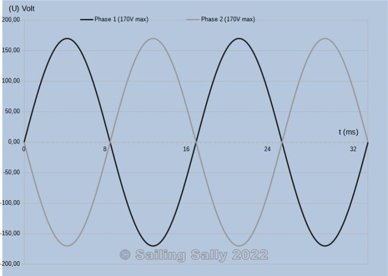
In a system like this with 2 phases, you can also connect equipment between the phases and then you get 240V RMS.
The image below shows how the RMS voltage varies in such a system.
Systems with one phase in USA
In an electrical system like this, there are 2 conductors and they are called Phase and Neutral. The nominal voltage difference between phase and neutral is 120V and the polarity is changed 60 times per second.
Summary AC
On a basic level, AC systems work in the same way, ie
- They have a voltage that constantly changes polarity according to a sine curve.
- They have one or more phases
- It is possible to connect equipment between a phase and zero / neutral
- It is possible to connect equipment between 2 or more phases
- The nominal voltage in the system is specified as an RMS value so that you can use Ohm’s law to calculate voltage, current, power and energy .
The main differences are
- What nominal voltage is used
- What frequency does the system use
- What is the phase shift between the voltage in different phases
- Name of the different cables used in the system
- Color coding of cables
- Design of wall sockets
- Design of power stations
- Connected equipment must be designed to handle the AC voltage they are connected to
Then of course there are a lot of other differences that have to do with cable standards (diameter, insulating casing, etc.) and electrical safety (protective earth, earth fault circuit breakers, fuses, design installation materials such as boxes, sockets, etc.
Since my purpose with the article series is to create an understanding of electricity and electrical systems, I will not go into detail on how installations should be done according to the various standards that exist.

Du måste vara inloggad för att kunna skicka en kommentar.