
In this and the next 2 articles, I make a description of an electrical system intended for a long-distance equipped newer boat around 40-60 feet with the possibility to connect 12V, 24V, and 230V equipment.
This article provides an overview of the electrical system with its components and the factors that influence its design.
Introduction
The electrical system of a sailboat like this consists of many electrical components that have different functions. Examples of these are batteries, battery chargers, control equipment for bow thrusters, lamps, switches, navigation instruments, various types of electrical fuses, etc.
If you have no previous experience or knowledge of electrical systems, you will be faced with a lot of new concepts, so take the time to really understand the function of the different parts and how they are connected.
The next article, part 3, will provide a more detailed description of the structure and functions of each subsystem. The article also contains a bit about the actual structure of the electrical system with electrical cabinets and the placement of equipment in the boat.
In part 4 I go through how an electrical drawing is structured with examples of an electrical drawing that includes certain parts of the different subsystems described in this and the next article.
Appendices to this article
You can read more about cable dimensioning in the article Electrical systems, part 2 – Dimensioning cables.
Explanation of symbols and description of the electrical components can be found in the article Electrical system, part 2 – Electrical components
Need for electrical subsystems
There are a few different things that affect which electrical subsystems are needed on the boat. Below I go through the most important aspects and how they affect which subsystems are needed.
- What form of electricity does the electrical equipment need
- How much power is required by electrical equipment that should be able to run at the same time
- The distance between producer and consumer of electrical energy
- How fault-tolerant the electrical system should be
1. Form of electricity
There can only be one form of electricity in an electrical subsystem. Since the boat has consumers who require different forms of electricity, 12V DC, 24V DC, and 230V AC, we need to divide the electrical system into at least three electrical subsystems, one for each form of electricity.
2. Power consumption and power balance
In the previous article, you also learned that a consumer requires a certain amount of power to function properly. The greater the power, the more current is consumed (the power formula).
The thickness of a cable limits the amount of current in it without giving too much voltage drop or overheating. The more power, the thicker the cable is needed to be. The longer the cable, the thicker the cable needs to be, see article on cable sizing.
There must be a balance between supplied and consumed power in an electrical subsystem. If there is a battery in the subsystem, it acts as a buffer and can store or give back energy.
This means that you have to size the supply of power so that the subsystem can supply the consumers with the power they need. Sum the power (P) of all consumers in the subsystem and calculate the maximum current (I) required with the power formula P = U * I, ie I = P / U where U is the nominal voltage in the subsystem.
Diesel generator
If the boat’s alternative energy sources (solar, wind, and water) produce less energy than needed, the batteries will supply the rest of the energy and after a while, they need to be charged. To avoid charging with the generator on the main engine, you can have a separate power plant that delivers energy for battery charging. On a boat with an electrical system like this with a 20 kWh battery bank, watermaker, and water heater, the diesel generator needs to be around 6 kW and generates approximately 25A 230V AC. With that effect, you can charge a 24V battery bank with 100Ah per hour, while making about 100 liters of water and heating 40 liters of hot water.
In a future article on batteries, I plan to write more about dimensioning of the battery bank, chargers, alternator, diesel generator, and generation from solar, wind, and water.
Shore power
For 230V AC, the current must not exceed what the fuse on the bridge can withstand. A good shore power connection has a fuse that is 16A, which means that a subsystem for 230V AC can have consumers who together draw a maximum of 16A.
This boat has electrical equipment that requires 230V AC, that may need more than 16A, so there are two subsystems for 230V AC. Each subsystem is connected to a separate shore power inlet.
Battery for 12V and 24V
While a large consumer is on in an electrical system that is to be powered by a battery, the battery must be able to supply the requested current without the voltage falling below 12V and 24V, respectively.
If the voltage drops below 12V and 24V respectively, other consumers may stop working, therefore there may be a need to separate large consumers from voltage-sensitive equipment.
3. Distance between producer and consumer
If the distance between the consumer and the component that provides electrical energy is long, the cables need to be thicker so as not to cause too much voltage drop or become too heated. A thicker cable is more expensive and more difficult to install as more space and special installation tools are required.
This can be handled by raising the voltage to 24V or 48V You can also build a separate subsystem with a battery close to the consumer.
The 24V Bow subsystem is an example of a subsystem that exists to create proximity between the power source (battery) and consumers with high power consumption.
In the article Electrical systems, part 2 – Dimensioning cables you can read more about how to calculate the thickness of the cables in different parts of the electrical system.
4. Fault tolerance
By dividing the electrical system into several subsystems, you can build electrical systems that can withstand faults better, eg when a battery is discharged.
The 12V Start subsystem is an example of this thinking. You have a battery that is only used to start the engine and it does not matter if the other batteries are discharged, it is still possible to start the engine.
Overview of electrical subsystems
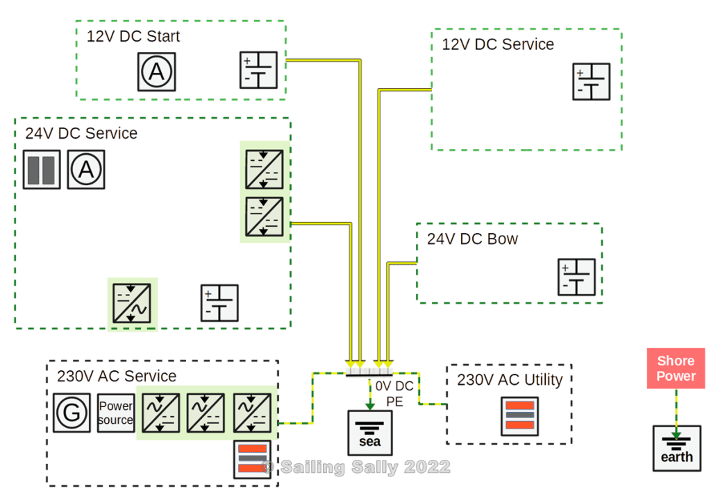
The above needs mean that the boat has six different electrical subsystems according to the picture below.
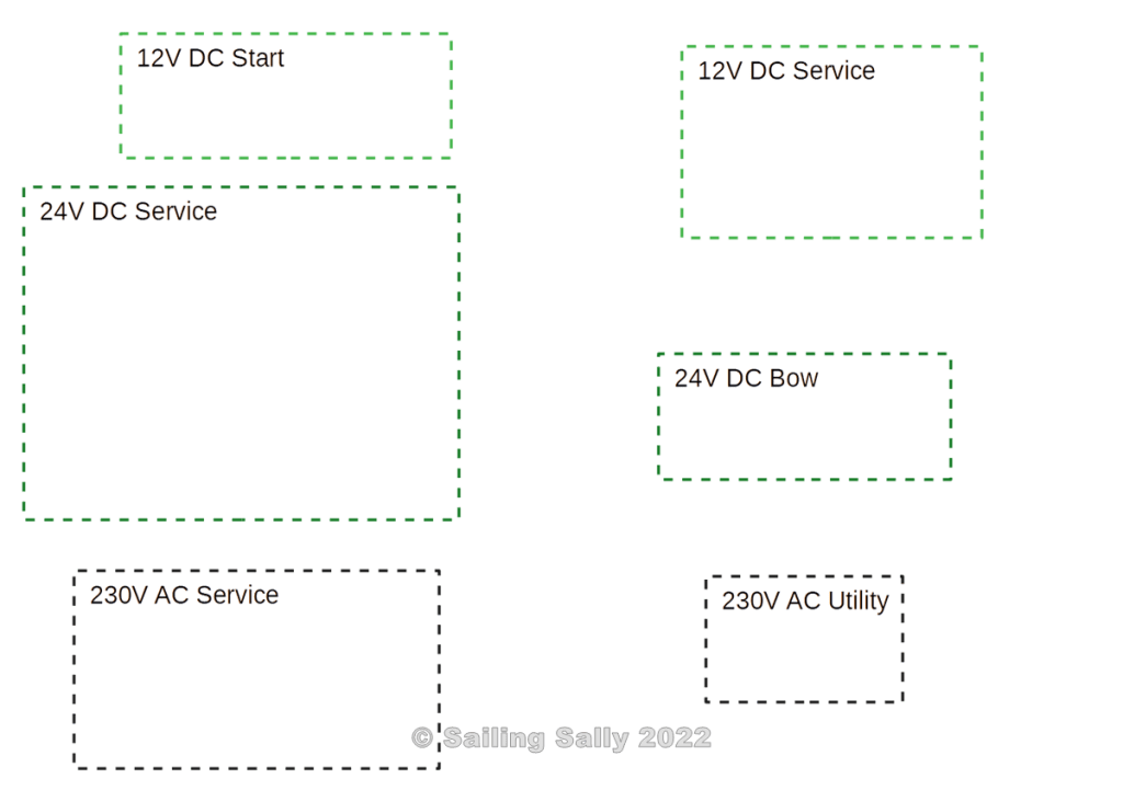
- 12V DC Start
This electrical system is used for the starter motor, motor sensors, and motor instrumentation. This subsystem exists on all boats with an inboard engine. - 12V DC Service
This electrical system is used to operate equipment that requires 12V DC, eg VHF, lighting, pumps, and navigation equipment. It has a larger battery capacity than 12V DC Start and thus it can store more energy. This means that the batteries supply more energy before they need to be charged. - 24V DC Service
This electrical system is used to drive equipment that requires 24V DC, such as lighting, pumps, navigation equipment, inverters, and so-called DC-DC converters to supply energy to the subsystems for 12V Service and 24V Bow.
An important motive for using 24V DC is that the current is halved and thus also halves the cable area compared to an electrical system that has 12V DC.
If you have a subsystem like this, this is where you usually have the most consumers, and thus the largest battery capacity. - 24V DC Bow
This electrical system is used to power equipment located in the bow of the boat which has great power (draws a lot of power when used). The battery is located close to the consumers to reduce the need for thick cables from a battery bank aft. In this case, it is a bow thruster and the electrical furlers for the forward sails that are operated.
Equipment that is sensitive to voltage drops is placed in 24V Service and is not affected by the use of the bow thruster. - 230V AC Service
This electrical system is available to operate equipment that requires 230V, such as a battery charger, washing machine, microwave, kettle, electric stove, or computer. As it is a 1-phase system that can handle a maximum of 16A, there are limits to how much power consumers can have. If you have read the previous article, you can calculate that 16A corresponds to the power P = 16A * 230V = 3.6kW (the power formula). The subsystem consists of 2 main circuits where only one of the circuits receives power when the inverter is running. - 230V AC Utility
This electrical system is also a single-phase system with a maximum of 10A usage and is available for equipment that requires additional power than what can be delivered via 230V AC Service. In our case, we find the boat’s Air Condition installed here.
Structure of the electrical system
In this section, I describe the structure of the electrical system by gradually adding functions to the various electrical subsystems in the following seven steps
- Deployment of batteries
- Deployment of energy sources
- Connection to electrical earth (grounding)
- Deployment of components for the transmission of electricity between different sub-systems
- Electrical interconnection of subsystems
- Deployment of high-power consumers
- Deployment of low-power consumers
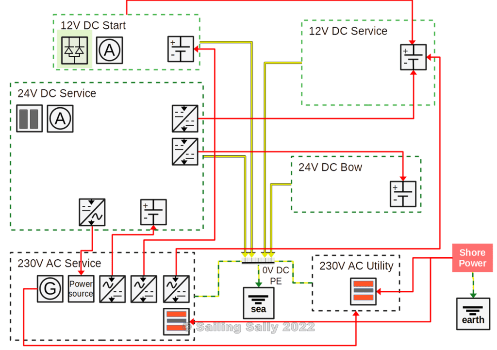
1. Batteries
The picture below shows which subsystems have batteries.
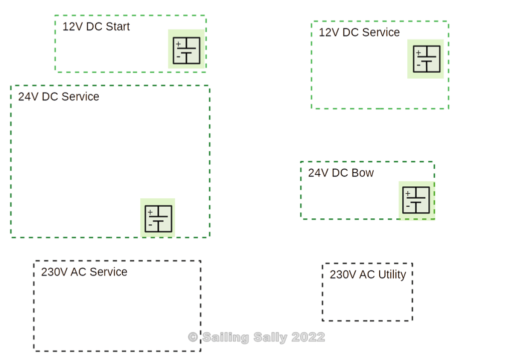
- 12V DC Start
Has a 12V AGM battery of 100Ah which corresponds to just over 1 kWh of energy. - 12V DC Service
Has a 12V LiFePo4 battery of 200Ah, which corresponds to just under 2.5 kWh of energy. - 24V DC Service
Has four parallel-connected LiFePo4 24V batteries of 200Ah, ie the capacity is 800 Ah, which corresponds to just over 19 kWh of energy. It is possible to use about 70% of the energy before the battery bank needs to be charged. - 24V DC Bow
Has two series-connected 12V AGM batteries of 150Ah, which corresponds to approximately 3.5 kWh of energy.
Note that both subsystems with 230V AC lack batteries and must therefore receive electricity from another subsystem, the diesel generator, or from shore power in order for the consumers to be able to be used.
I will return to dimensioning of battery capacity in a future article on Batteries.
2. Energy sources
Energy for the electrical system comes from shore power, solar panels, wind and water generator, a diesel generator, and alternators on the main engine. The diesel generator and the alternators on the main engine convert the energy in the diesel fuel into electricity.
The generated electricity can be used directly by connected consumers and the surplus is stored in the boat’s batteries until these are fully charged. When there is no need for energy, the regulator for each of the producers ensures that the energy source does not create any electricity even if, for example, the engine is running or the solar panels are illuminated by the sun.
In the picture below I have added the boat’s energy sources and equipment to connect shore power to the boat’s electrical system.
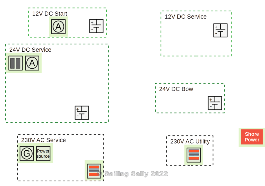
- 12V DC Start
90A 12V alternator on the main engine - 24V DC Service
110A 24V alternator on main engine and 800W of solar panels. - 230V AC Service
Diesel power generator 6kW, 230V AC
Shore power up to 16A 230V AC
One unit (Power source) for source selection for 230V AC (shore power, inverter, diesel generator) - 230V AC Utility
shore power up to 10A 230V AC.
Note that the subsystems 12V DC Service and 24V DC Bow lack their own energy sources. This means that these subsystems must get energy for their batteries from other subsystems, see section Conversion of electricity to another subsystem.
3. Protective earth in 230V and 0V in 12V/24V
There are a few different principles about how 0V and protective earth should be connected in a boat.
In the US, there is a rule that says that you must connect all metal parts underwater in an internal so-called Bonding system and connect it to an external zinc anode to protect the metal parts from galvanic corrosion. The bonding system is in turn connected to 0V and protective earth.
To prevent corrosion when connected to shore power, an isolation transformer must be used. The use of a so-called zinc saver on the protective earth does not provide sufficient protection in all situations.
In Europe, we do not have a rule like this, which means that there are several different ways to handle 0V and protective earth in a boat.
Since this sailboat has an electrical system that can be connected to shore power for a long time, we use almost the same method as in the US. The difference is that only the metal parts under the water that have indirect contact with 0V or protective earth are connected and connected to an external zinc anode and earth plate. More about this in a later article on grounding.
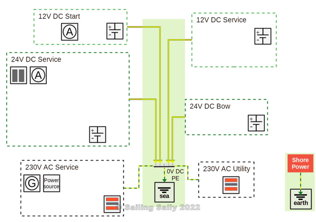
The subsystems for 12V DC and 24V DC have 0V (battery minus) connected to a common 0V terminal in the boat.
The subsystems for 230V AC have their protective earth connected to the common 0V terminal, which in turn is connected to the boat’s external grounding plate and to a zinc anode.
4. Conversion of electricity
Since some subsystems do not have their own energy source or battery, there need to be electrical connections between the subsystems so that energy (electricity) in one subsystem can be converted and transferred to another subsystem.
In this image, I have added the components used to convert energy in one subsystem to the correct form of electricity for another subsystem. This includes chargers, converters, and inverters.
- 24V DC Service
Converter for 24V to 24V 30A that charges the bow battery
Converter for 24V to 12V 30A that charges the battery in 12V Service
Inverter 24V to 230V 16A AC which supplies 230V Service with electricity - 230V AC Service
A 12V 15A charger for battery in 12V Start.
A 12V 35A charger for battery in 12V Service.
A 24V 100A charger for Battery in 24V Service.
5. Interconnection of subsystems
The purpose of these connections is to supply another subsystem with electricity (energy).
This means that each system does not need to be able to generate or store the right type of electricity for its consumers. It can also increase the fault tolerance of the electrical system by making it possible to get electricity from several sources.
The red lines between the subsystems show the electrical connections between the subsystems.
- 12V DC Start
An alternator on the main engine that can charge the battery in 12V Service via a battery separator - 24V DC Service
DC/DC Converters that charge the batteries in 12V DC Service and 24V DC Bow. An inverter that is connected to 230V Service - 24V DC Bow
The battery is charged by a DC/DC converter in 24V Service - 230V AC Service
Chargers are connected to 12V Start, 12V Service, and 24V Service
Connection to 230V AC Utility so that the diesel generator can supply electricity to that subsystem.
Connection from shore power - 230V AC Utility
Connection from shore power
Connection from the diesel generator in 230V AC Service.
You could remove the battery in 12V Service and instead have a converter in 24V Service that powers all consumers in 12V Service. In that way, you could remove the 12V charger in 230V AC Service and also the battery separator in 12V Start. The disadvantage is that it is not possible to make an Emergency connection from 12V Service to 12V Start as described in the next chapter.
6. Consumers with large power
Consumers that have large power, may need to be placed in their own subsystem because when used the voltage will drop below 12V. Eg starter motor, bow thruster, and anchor winch. They also require an energy source that can withstand delivering the power they need. Not all motors have a soft start and draw more than twice as much current when they start (starting current) as when running. Large currents also mean that cabling needs to be thicker the longer the distance to the battery. In our case, the starter motors and bow thruster have been placed in subsystems with their own batteries.
Note that the anchor winch is not located in the 24V DC Bow. The reason is that it is conceivable that you need to use the bow thruster at the same time as you use the anchor winch. This would place even greater demands on the power that the battery bank in the bow should be able to deliver.
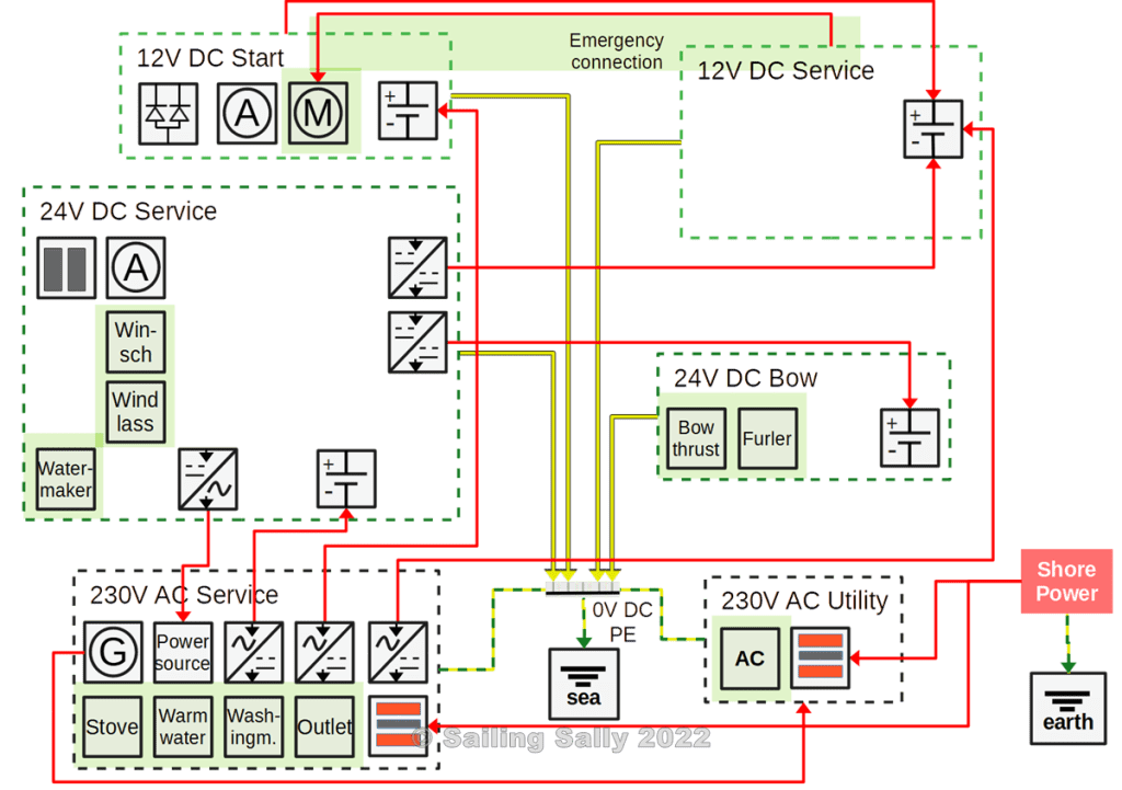
- 12V DC Start
The starter motor on the main engine and a starter motor on the diesel generator.
We have also added an emergency connection to 12V Service which makes it possible to start the motor even if the battery in 12V Start is discharged. - 24V DC Service
Winches, watermaker, inverter, converters - 24V DC Bow
Bow thruster, furler for the forward sails - 230V AC Service
Stove, water heater, washing machine, vacuum cleaner, and tools connected to wall sockets. - 230V AC Utility
Air conditioning
7. Consumers with small power
Now all remaining consumers are deployed and they end up in the subsystems for 12V Service or 24V Service. Some instruments have been duplicated and placed in different subsystems for increased fault tolerance.
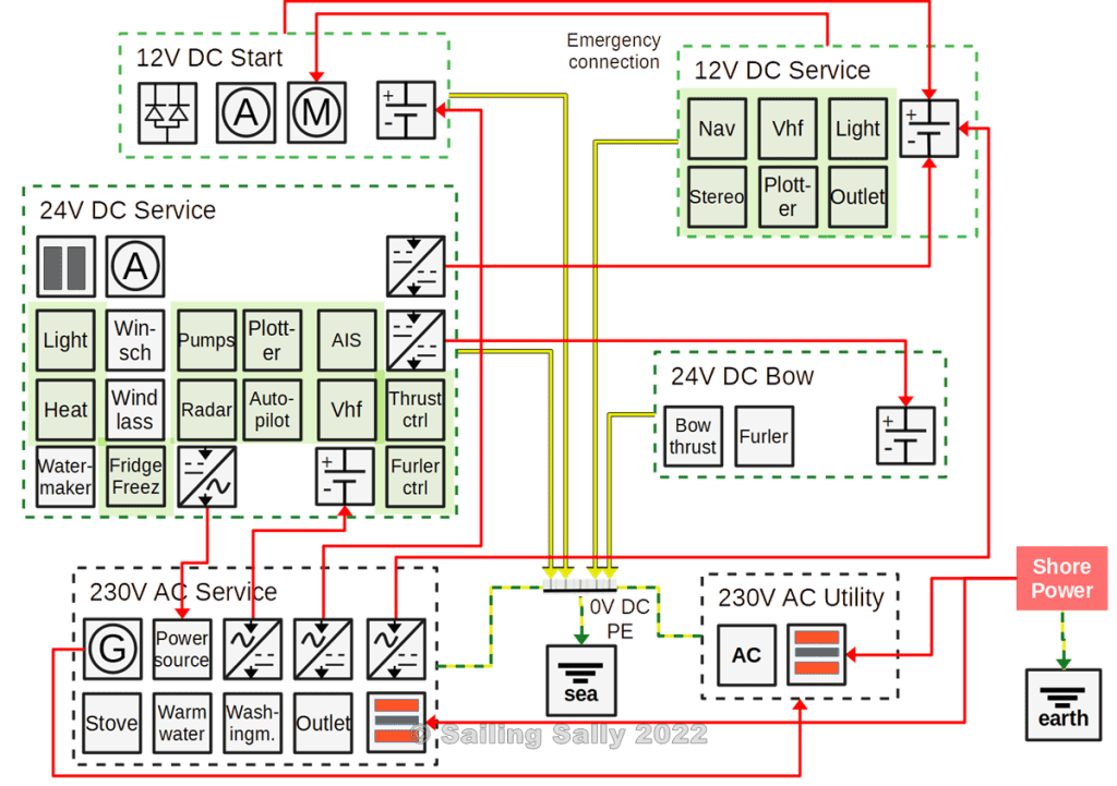
- 12V DC Service
Extra Vhf, lighting, stereo, USB charger
A chart plotter and some navigation instruments with sensors - 24V DC Service
Lighting, pressurized water pump, bilge pump, plotter, radar, AIS with GPS, Vhf, heater, refrigerator, freezer, and autopilot. Note that the control boxes for bow-thruster and forward furler(s) are placed in another subsystem than the controlled device. The reason is that the voltage in 24V DC Bow may drop too much for the control boxes that require a stable voltage of 24V.
Everyday electronics
It is often not possible to connect directly to 12V DC or 24V DC so it is easiest to have an inverter on board. Then you can connect monitors, computers, and adapters without any problems. So bring original adapters to your everyday electronics, it saves a lot of work with the electrical system.
Phones and tablets are charged with a USB charger and such are available for 12V either to plug into a 12V car socket or for fixed mounting in the boat, eg in connection with places where you stay a lot (at the bunk, at the sofa in salon).
These small standardized USB chargers deliver 5V and a certain maximum current (USB2 provides 500mA and USB3 gr 900mA) which is too small for a modern smartphone or tablet. So bring the original charger for 230V AC if you want to be able to charge fast and keep the battery in good condition.

Du måste vara inloggad för att kunna skicka en kommentar.