
In this article, you can read if you use a so-called multimeter (measuring instrument) to measure voltage, resistance, and current. I would like to say that it is your most important measuring instrument to be able to troubleshoot the electrical system.
The multimeter, your most important measuring instrument on board
If you do not have a multimeter onboard, get one!
There are multimeters for professionals that cost several hundred Euros and there are simpler multimeters that cost 20-30 Euros. For most situations you are faced with, a simpler multimeter is sufficient, which in some cases can also be equipped with pliers to measure electrical currents.
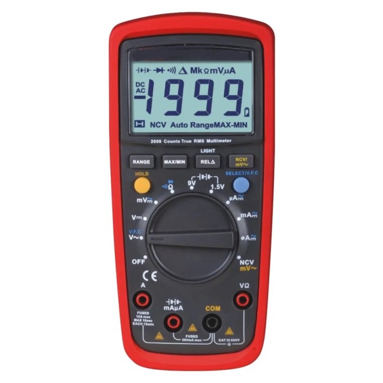
With a simple multimeter, you can measure these electrical properties with sufficient accuracy if the battery in the multimeter is in good condition.
- DC voltage, different measuring ranges are specified with V⚎ or mV⚎
Unit V or mV (milli V, thousandths of a volt)
Sometimes they have automatic setting of measuring range and then it is enough to choose measurement of DC voltage V⚎ - Alternating voltage, different measuring ranges are indicated by V ∼ or mV ∼
Unit V or mV. Sometimes they have automatic setting of measuring range and then it is enough to choose measurement of alternating voltage V ∼ - Direct current, often denoted by A⚎ or mA⚎
Unit A or mA (milli A = thousandths of an ampere) - Electrical resistance, different measuring ranges are indicated by Ω, kΩ or MΩ and sometimes the permitted min and max value is also stated
Unit Ω, kΩ or MΩ (kilo Ω = 1000 Ω , mega Ω = 1 million Ω) - Electrical contact, ie that the resistance is very low
When in contact, the multimeter emits a signal - Contactless measurement if a cable is live
When the cable is energized, the multimeter emits a signal - Contactless measurement of current in a cable (pliers multimeter)
- Voltage drop across a semiconductor called a diode
Connection of measuring cables
The multimeter’s red and black measuring cables must be connected in different ways depending on what is to be measured. Read the instructions for your multimeter for detailed information. Sometimes there are 3 sockets in the multimeter and sometimes 4 as in the picture above. There are some things that are always the same and that is
- A black socket where it says COM
Here the black measuring cable is always connected - One or two sockets for the red measuring cable when measuring current
If the multimeter can measure strong current, up to 10A, it is often a separate socket for that measuring range - A socket for the red measuring cable when measuring voltage and resistance and if there is electrical contact between two points.
Measurement with multimeter
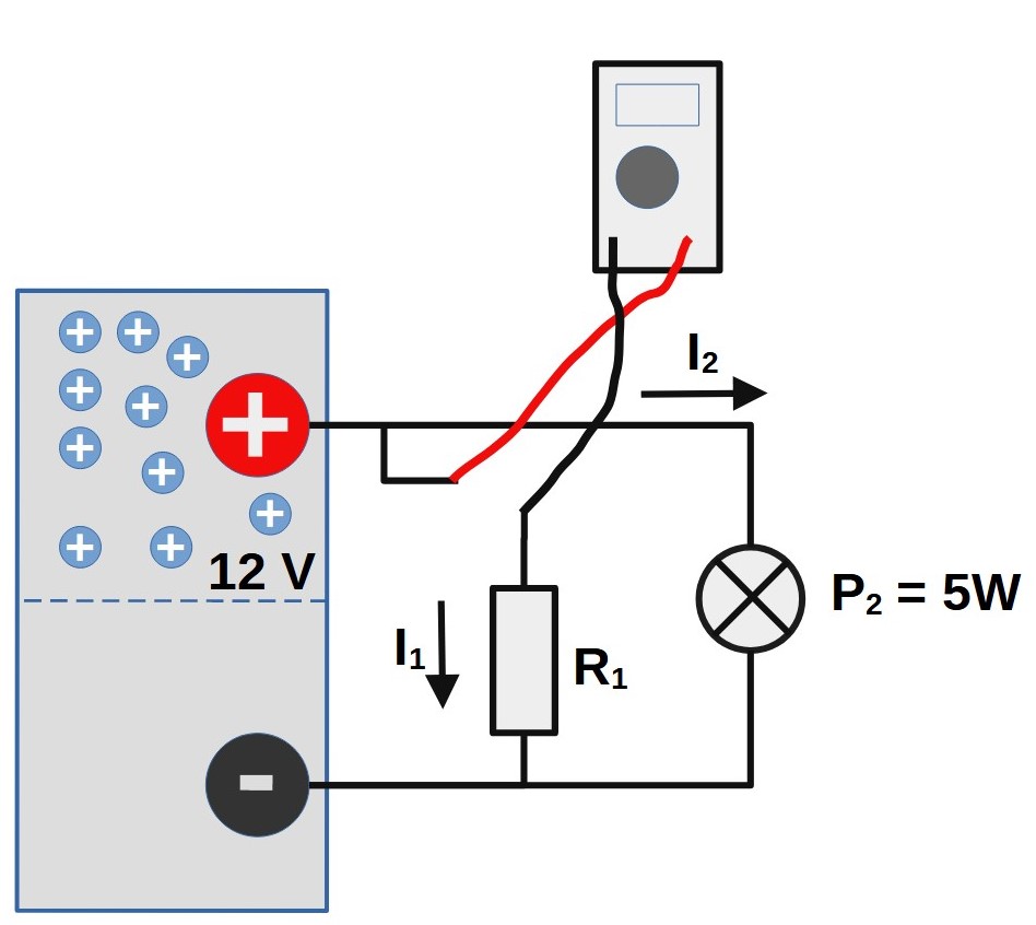
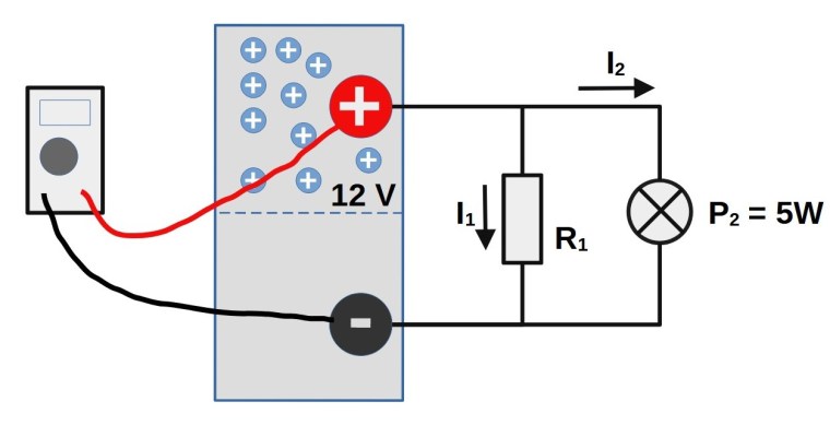
I will use a simple electrical system to show where to connect the multimeter when you want to measure a certain property in the system. The electrical system consists of the following interconnected parts.
- A 12V battery
- A consumer with resistance R 1 that draws power I 1
- A lamp that is connected in parallel with the consumer. The power of the lamp is P 2 = 5W and draws the current I 2 A.
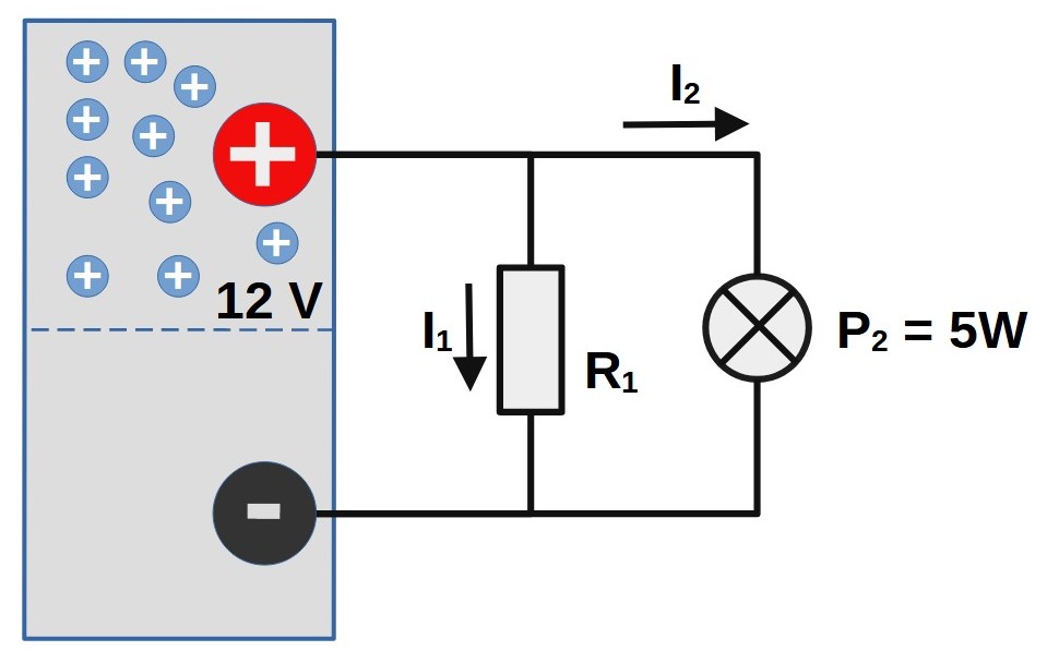
If we want to find out how much power is used by the system, we need to find out the power of the consumer. How do we do that?
There are three ways to find out the effect of the consumer
- If you have technical info about the consumer, the information on electrical power consumption may be found there and you are done 🙂
- Measure its resistance R 1 and then calculate the current with Ohm’s law according to I = U / R.
- Measure the current that passes through the consumer.
Measure resistance
If it is easiest to measure resistance, the consumer first needs to be disconnected. If it is connected, you will also measure the resistance across the battery and the lamp as these are connected in parallel with the lamp. It gives the wrong value for the consumer’s resistance (too low value).
- Disconnect the consumer
- Set the multimeter to measure resistance, start with a large range, eg 0-200Ω.
- Connect the multimeter’s measuring cables to plus and minus the connection on the consumer and read. It does not matter if you connect the red measuring cable to the plus or minus connection on the consumer. If you get a value that is too low, try changing the measuring range to a slightly smaller range.
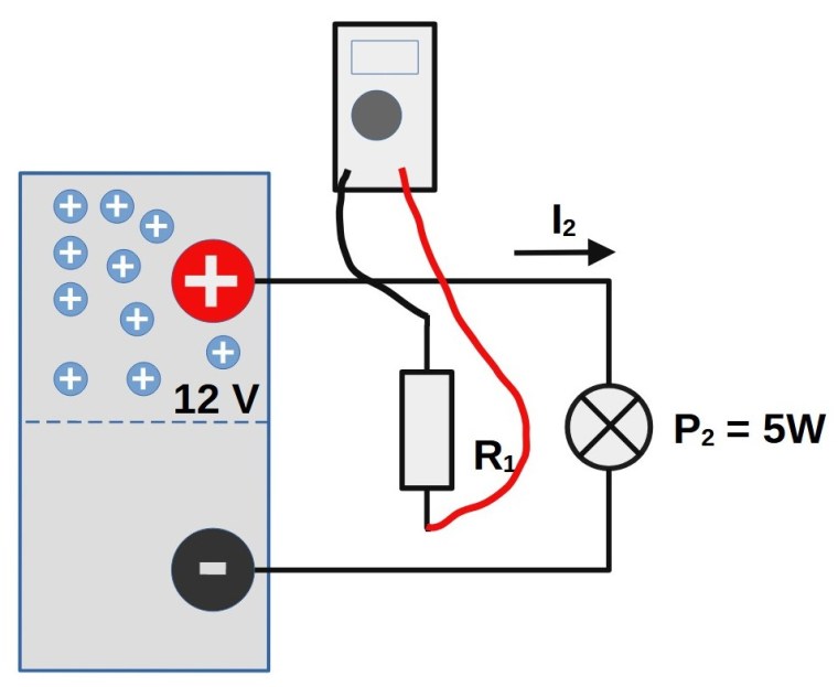
When we know the resistance, we can calculate the current with Ohm’s law I = U / R. If we assume that the measured resistance became 8Ω, the current becomes
I1 = 12/8 = 1,5A which result in P1 = U*I = 12*1,5 = 18W
Measurement on electric motors and other nonlinear components
Measuring resistance in this way only gives the right result as long as the consumer is not an electric motor or other nonlinear equipment. In these cases, all that remains is to measure the current to the equipment in order to be able to calculate the effect.
Measure electrical current
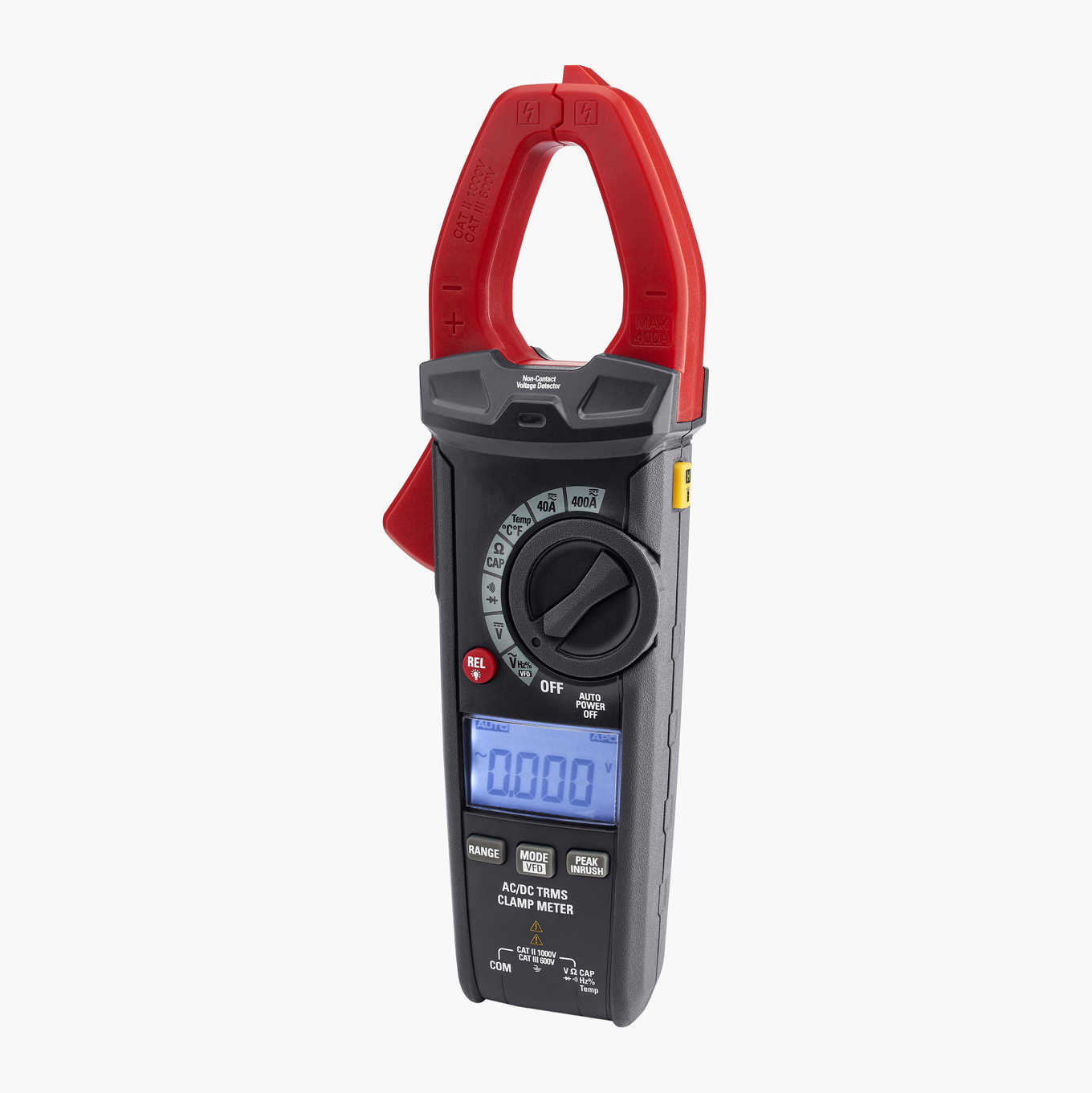
If we want to measure the current through the consumer, we can do so in two ways. Either use a pliers multimeter to measure current or connect the multimeter’s measuring cables in series with the consumer. To be able to measure the current, the consumer must be running. If a motor uses more than 2A or so, then it works best with a pliers multimeter that can measure large currents without having to disconnect the electrical system. Electronic equipment often draws little power and then you can measure it with a standard multimeter.
Measure current with pliers multimeter
- Before you start measuring, set it to measure current with the pliers.
- Open the pliers and place it over the consumer cable and close it completely (important).
- Read the measured current value. Measuring with a pliers multimeter does not give an exact value for the current, but you get an idea of its size. Works best when you have high currents such as from a charger or to an electric motor.
If we assume that the measurement shows a current that is 1A, we use the power formula P = U * I which gives that
Electrical power P1 = 12V * 1A = 12W
Measure current with multimeter
- Before you start measuring, make sure that the multimeter can handle the current flowing through the consumer. Standard multimeters often have a limit of 10A.
- Turn off the consumer and disconnect its plus or minus cable.
- Connect the multimeter’s measuring cables in series so that the red measuring cable is connected to the plus- the side and the black on the minus side. Make sure there is good contact. It does not matter if you connect before or after the consumer. In the picture below, the multimeter is connected before the consumer.
- Set the multimeter to a large measuring range, eg 0-10A.
- Start the consumer and read the current, if it is a low value, reduce the measuring range on the multimeter. We assume that the measured value will be 1.45A.
Now we can calculate the electrical power in the same way as before and get
P1 = 12V * 1,45A = 17,4W
Total electrical power of the system
Now we can calculate the total power of the electricity system the sum of the effects of the consumers and the lamp.
The consumer’s effect is a bit uncertain because our different measurements gave slightly different results.
- Resistance measurement gave P 1 = 18 W
- Current measurement with pliers multimeter gave P 1 = 12W
- Current measurement in series gave P 1 = 17.4W
A reasonable conclusion from this is that the consumer has a power that is approximately 18W and if we use it becomes
The total electrical power is P = 18 + 5 W = 23W
Measure DC voltage and AC voltage
Simpler multimeters often have a few different settings to choose whether to measure direct voltage or alternating voltage, as well as which voltage range you are measuring, eg 0-20V or 0-200V.
The measurements are done in the same way, only different settings of the multimeter are made
- Select measuring range, direct voltage or alternating voltage.
- Connect the multimeter’s measuring cables to the two points in the electrical system where you want to measure the voltage, eg the red cable on the battery’s positive pole and the black at the negative pole.
- Read
If we assume that the reading shows that there is 12.8V between the battery’s poles, it is a perfectly OK value because the battery’s voltage depends on how much it is charged and how much power is taken out of it at the time of measurement.
Measure if there is an electrical contact
This measurement is useful if you want to find out if there is an electrical contact between different parts of the electrical system or between other points on the boat, eg when you want to check if a part of the boat is in contact with the electrical ground or not. Such electrical contacts between different parts of the boat and electrical systems are of great importance for galvanic and electrical corrosion. I will write more about this in my own section at the end of the article series.
- Set the multimeter to measure electrical contact
- Connect the multimeter’s measuring cables to the points you want to check if there is a connection between them
- If the multimeter emits a signal, it is not a contact .
Measure voltage drop of a diode
A diode is an electrical component that only conducts current in one direction. They start conducting current when the voltage reaches a certain level, often around 0.7V. This voltage drop is called the forward voltage drop. In the other direction, the diode conducts current when the so-called reverse voltage is reached. That voltage is much higher, several hundred volts and up.
Before the forward voltage is reached, the diode has a very large resistance, ie it conducts almost no current at all. When it starts to conduct current, the resistance drops to almost zero, but the voltage drop remains all the time.
The picture below shows what diodes look like in an electrical drawing. They conduct current in the direction of the arrow.
To measure the voltage drop on a diode, do the following
- Disconnect the diode from the system
- Set the multimeter for diode metering
- Connect the red measuring cable on the positive connection of the diode and the black measuring cable on the negative side
- Displays the multimeter 0, try changing the position of the measuring cables. If it still shows 0V, the diode is faulty and needs to be replaced.
- If the multimeter shows a higher value, the diode is probably faulty.
To measure the reverse voltage of the diode, do the following
- Do steps 1 and 2 above
- Connect the red measuring cable to the negative connection of the diode and the black measuring cable to the positive side.
- If the multimeter shows infinite voltage, the diode works properly .
- If the multimeter shows a lower value, the diode is probably faulty.

Ett svar till “Electrical systems, part 1 – The multimeter”
[…] Hur man använder en multimeter […]
GillaGilla