
In this article, I go through the design and function of the main circuits in the electrical subsystems. The article also describes several of the components and circuits of the subsystems in separate appendices. That makes this article the most comprehensive one in the series.
Introduction
Articles are meant to be read in the order they are published, so feel free to go back and repeat previous articles if there is something you do not recognize.
When reviewing the function of the various subsystems, connected subsystems are also plotted to show where the interconnections are going.
Appendices to this article
Appendice Electrical System, Part 3 – Symbol description describes what the different symbols of the electrical drawings mean and what function they have in the electrical system. Some symbols are the same as in the previous article and they are described in Electrical System, Part 2 – Electrical components.
In the other appendix, Electrical Systems, Part 3 – Circuits, you can read more about what an electrical circuit is.
There are more planned appendices to this article that covers
- Data network for components of the electrical system
- The electrical system on the engine
- Alternators
- Connection to shore power
- Diesel generator
- Solar panels
- Wind generator
- Hydro generator
- Practical topics related to the electrical installation
12V DC Start
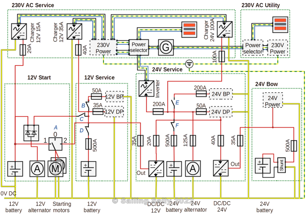
The main function of this subsystem is to supply the starter motors with power and to charge the batteries in 12V start and 12V Service when the engine is running.
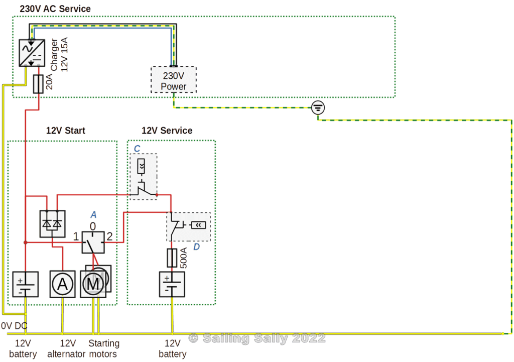
The battery selector at A connects the starter battery to the starter motors in position 1. In position 2, it connects the battery in 12V Service to the starter motors (Emergency connection).
The starter battery can also be charged with up to 15A from a charger in 230V Service.
The generator on the motor supplies power to both 12V Start and 12V Service via the battery separator. When the battery in 12V Service is charged, the battery disconnects the charge using the remote control switch at C which is also connected to the network. During this disconnection, something called ”Load dump” may occur. You can read more about this in the appendix on the generator.
12V Service
The function of this subsystem is to supply 12V equipment with power. The equipment is connected on two main circuits, one for equipment that must have power at all times, Direct Power (DP). Equipment that only needs to run when you are on the boat, is connected to the other circuit for Breaker Power (BP).
It also has the task of being able to be used in an emergency to start the engine by changing the position of the battery selector at A.
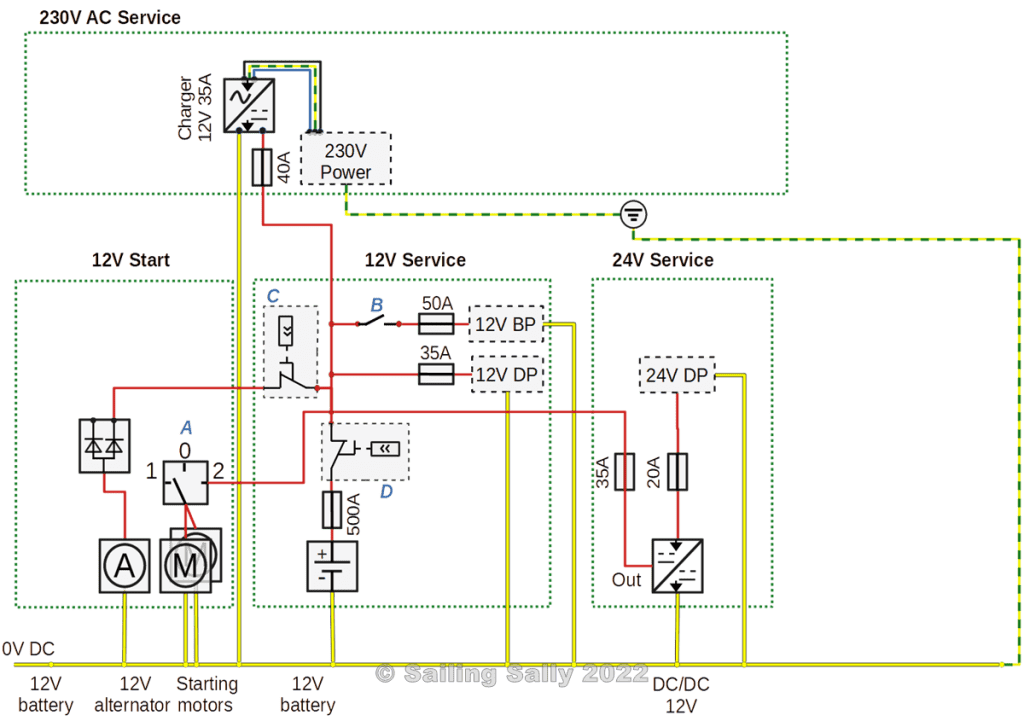
The B main switch is used to connect power to the Breaker Power circuit.
The C switch is remotely controlled by the battery via the network and disconnects the charge from 12V Start when the battery is fully charged.
Since it is a monitored LiFePo4 battery, there is a D remote power switch that disconnects the battery before it becomes too discharged.
There is also a fuse that disconnects the current to/from the battery if it exceeds 500A.
The battery can be charged from three different sources
- The 12V alternator on the main engine can charge with up to 90A
- The DC/DC converter in the subsystem for 24V Service can charge with up to 30A
- Charger in the subsystem for 230V Service that can charge with up to 35A
24V Service
This electrical subsystem has several different functions
- The function of this subsystem is to supply 12V equipment with power. The equipment is connected on two main circuits, one for equipment that must have power at all times, Direct Power (DP). Equipment that only needs to run when you are on the boat, is connected to the other circuit for Breaker Power (BP).
- Supply 230V AC with electricity via an inverter
- Charge the battery in 12V Service
- Charge the battery in the 24V Bow

The E main power switch is used to connect power to the Breaker Power circuit.
Because it is a supervised LiFePo4 battery, there is a remote power switch F that disconnects the battery before it becomes too discharged.
There is also a fuse that disconnects the current to/from the battery if it exceeds 500A.
The main fuses for the various circuits in 24V Service are shown in the electrical drawing, for example, the Inverter has a fuse of 250A.
The 24V Service battery can be charged
- Charger in 230V AC, the charger is supplied with power from shore power or diesel generator.
- 24V generator on the main engine
- Solar panels, wind, and hydro generator
24V Bow
This subsystem has the task of supplying bow thrusters and electric furlers for the fore sails with power.
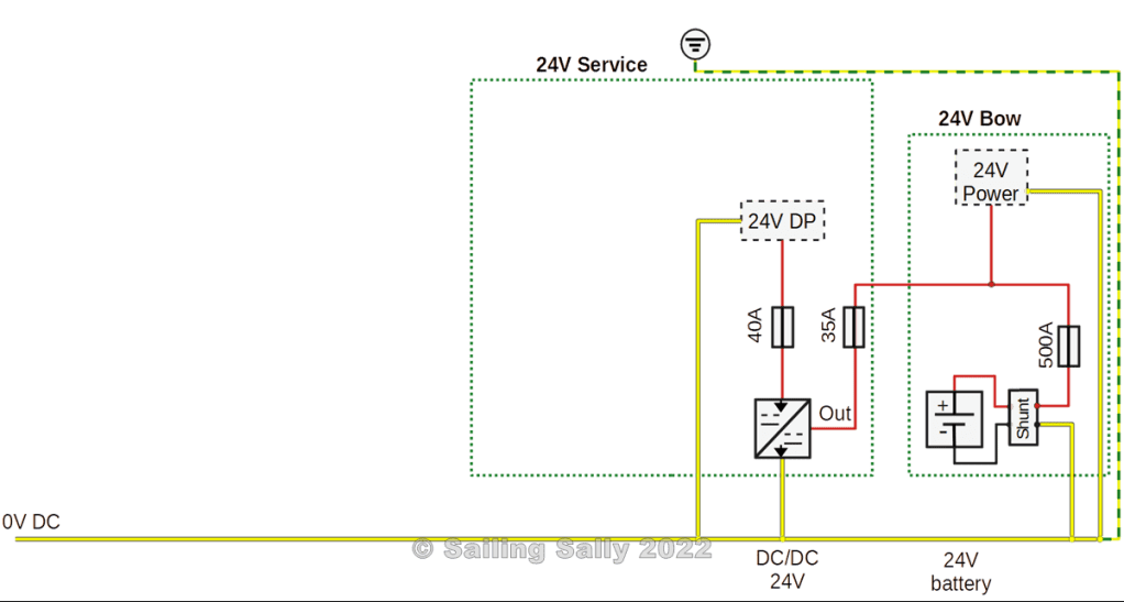
It may happen that the bow thruster and anchor winch are used at the same time, so in order not to place too great demands on power output from the bow batteries, the anchor winch is connected to 24V Service. The batteries in 24V Service are able to deliver power without the voltage dropping below 24V, especially as you probably also run the motor when using the windlass and thus supply power from the 24V generator.
The battery is charged from a converter in 24V Service that provides up to 30A. The converter is connected to the circuit with Direct Power (DP) in 24V Service. This means that the converter is running even if the main switch in 24V Service is switched off.
There is a fuse that disconnects the current to/from the battery if it exceeds 500A.
The shunt is used to measure the current to/from the battery and thus be able to calculate how much charge the battery has. It is connected to the network and the DC/DC converter uses it to control the charging of the bow battery.
230V Service
Personal protection
All main circuits for 230V AC must be equipped with their own earth-fault circuit breaker. All consumers must be connected to the boat’s local protective earth.
Installation and modification of electrical systems with 230V AC must be performed by a qualified electrician.
Purpose
The purpose of this subsystem is to supply electricity to consumers who need 230V AC 50Hz.
The subsystem can connect to the following 230V AC sources
- Shore power
- Diesel generator on board
- Inverter available in 24V Service
The drawing below shows the main circuit of the subsystem
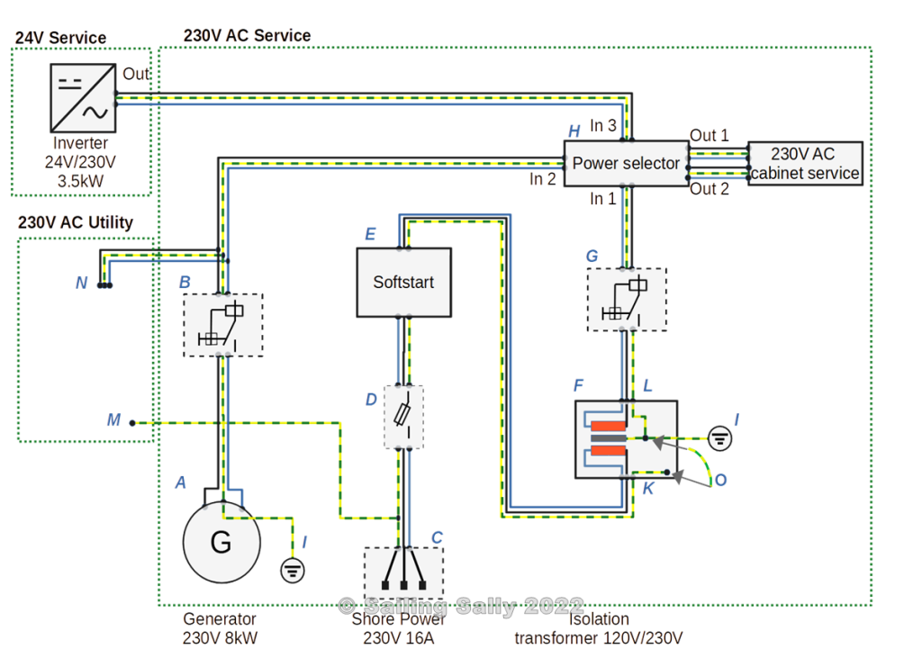
The diesel generator A is connected via B, a fuse combined with an earth fault circuit breaker G, to the Power selector at H (equipment that selects which source for 230V AC that should be connected). The power plant is also connected to point N in the 230V AC Utility.
The connection for shore power C, goes via the fuse D, to E, a soft starter, and then on to the primary side (K) of an isolation transformer F.
The secondary side of the isolation transformer (L) is connected to the earth fault circuit breaker G which in turn connects to the Power selector at H.
The isolation transformer F means that there is no metallic contact between the boat’s electrical system and the electrical system on land. In this way, galvanic corrosion due to the electrical system ashore is avoided.
Connection from Inverter in 24V Service is connected to Power selector at H.
The power selector at H makes it possible to automatically connect any source for 230V AC to the boat’s electrical cabinet to which all 230V AC consumers are connected. Should several sources have voltage at the same time, they are selected in order of priority
- Shore power
- Diesel generator on board
- Inverter in 24V Service
The power selector H has two outputs Out 1 and Out 2 which form two different circuits in the main cabinet for 230V AC. These outputs are used to select which equipment can be used depending on where the power comes from.
The recommendation is that Out 1 always receives power as soon as there is power available. Out 2 only receives electricity when shore power or the diesel generator provides electricity.
By connecting all the chargers on Out 2, they can not be used when the inverter leaves power. The water heater may also belong in this circuit (heating water is quite energy-intensive).
Protective earth
The protective earth of the diesel generator is connected to the boat’s protective earth.
Protective earth in the shore power connection protects equipment up to the primary side of the isolation transformer (K). The housing of the transformer is connected to the boat’s protective earth.
The secondary side of the isolation transformer (L) has protective earth connected to the boat’s protective earth (I). Note that the isolation transformer housing is also connected to the boat’s protective earth.
When the boat is on land, the boat’s protective earth should be connected to shore power. This is done by connecting the protective earth on the primary side of the isolation transformer to that on the secondary side (at O in the drawing).
There is also a connection between the protective earth on the shoreside and the protective earth in 230V Utility (N). This means that the protective earth of the primary side of 230V Utility is always connected to the ”correct” protective earth, whether the boat is in the water or on land.
230V Utility
Personal protection
All main circuits for 230V AC must be equipped with their own earth-fault circuit breaker. All consumers must be connected to the boat’s local protective earth.
Installation and modification of electrical systems with 230V AC must be performed by a qualified electrician.
Syfte
The purpose of this subsystem is to supply the boat’s AC system with 230V AC when the boat is connected to shore power.
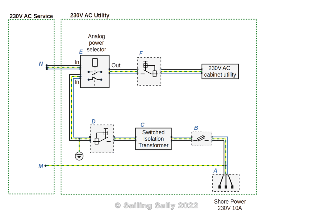
The shore power connection A connects via a fuse B to the primary side of the isolation transformer C. The secondary side of the isolation transformer is connected to an earth fault circuit breaker D which in turn is connected to a power selector E which selects whether shore power or diesel generator is to supply the electrical cabinet with power via an earth fault circuit breaker F.
In this case, we have chosen another type of isolation transformer that uses so-called switched technology. This means that you can use a smaller and thus lighter transformer. There are no large consumers in this subsystem that use a lot of power directly (battery chargers or water heaters) and thus no equipment is needed to limit current (a soft start device) when shore power is connected.
Protective earth
Protective earth in the connection for shore power protects equipment up to the primary side of the isolation transformer, but not the housing of the transformer itself.
The secondary side of the isolation transformer has protective earth connected to the boat’s protective earth. Note that the isolation transformer housing is also connected to the boat’s protective earth.
Since the protective earth on the secondary side of the 230V Utility is connected to the boat’s protective earth, the secondary side protective earth is always connected to the correct protective earth, regardless of whether the boat is in the water or on land.
Connection N means that the primary side protective earth in 230V Utility is always connected to the ”correct” protective earth, regardless of whether the boat is in the water or on land.

Du måste vara inloggad för att kunna skicka en kommentar.